Wednesday, February 20, 2013
Labs for switching
Ok practice makes perfect.
Almost all of the Material that Juniper gives in the LABs is very badly explained.
So you will have to make your own material using theirs as a base.
To be honest I tried labbing most of the items here.
The SRX however does not behave like an MX.
So barring access to an MX, you will not be able to lab the Switching part.
You will also run into difficulties with the MPLS labs.
You can lab the Routing part as these are routing protocols.
The Juniper Partner portal has an online virtuallabs
however it is set up to follow like a parrot and is not useful for beginners.
I passed the Exam barely.
Since I can't afford $30K worth of Demo equipment.
I will be sticking to the other tracks.
Good luck on the exam.
My material is in the rest of the blog.
Study the appendixes in the books too. Especially ISIS.
Saturday, February 16, 2013
MPLS and Vlans - ma favorite
Basics

IGP .
So we learned in the routing part that you can route traffic.
The traffic being routed will take the best choice.
For RIP it will be 1-2-3-6-8-www even though this is the most expensive 8
For OSPF and ISIS it will be 1-2-4-5-6-8-www which is the least expensive 6
So we pick one and what will happen is all the traffic will mainly flow on that route.
So router 3 and 7 are under utilized.
The goal of a good IT budgeting department is always to maximize the utilization of devices.
That way you don't have to upgrade as much.
Let's say you upgrade link 3-6 so now the cost is 1. Well then routers 4-5-7 will be underutilized.
So you just moved the problem around.
OK, back in 2K we had a network called ATM.
Asynchronous Transfer Mode.

Very complex, however it allowed each node to carry statistics on the data travelling on it.
It also allowed the routes or connections to change if links along the way were being saturated.
For example if 8 to 9 was congested a bit would go back along the route
and the Virtual connection would switch to 6 to 7 to 9. Till the route was back to not being congested.
The downside of the above ATM, was you needed to hire
an ATM expert and an IP expert as each was similar but very different.
The second downside was that ATM packets had a fixed size.
This is similar to a train car.
So if the TCP packet was an Acknowledge (ie 2 people) then the rest of the train car
was pretty empty. You still needed a train to pull the car along (Headers)
The third one was the number of links from devices to devices was very large as you required
a Mesh to leverage it.
The same problem happens with Frame-Relay which is another technology from 2K.
So in comes the solution in the name of MPLS.
Since Ethernet is cheaper and IP more abundant.
MPLS is seen as the wave of the future.
In general the MPLS is considered the Forwarding infrastructure
So in MPLS instead of doing long IP looksup. They use short labels.
A label is Pushed on the packet.
The MPLS Service Provider now uses Short Labels to decide where to send the traffic
The last or penultimate device will Pop the label.
Notice how this is similar to the QinQ idea.

Let's move on, an MPLS Header is composed of :

The Label is easy.
The COS was a nice idea but nobody uses it.
Bottom of Stack is for when you want to Stack inside a Stack
The limit is three at ingress and unlimited at transit.
TTL is intelligently copied from the IP packet and then at every hp is decremented by the MPLS routers.
Reserved labels are
0-3 have some guidelines on popping.
4-15 are reserved for future use.
The Database for MPLS is called the LIB
Label Information Base.
It is stored in a table called mpls.0
When this table is created it automatically creates Labels.
1. Label 0 IPv4 null
2. Label 1 Router Alert
3. Label 2 IPv6 null.
The table itself will have the following structure.
user@host> show route table mpls
mpls.0: 4 destinations, 4 routes (4 active, 0 holddown, 0 hidden)
+ = Active Route, - = Last Active, * = Both
0 *[MPLS/0] 00:13:55, metric 1
Receive
1 *[MPLS/0] 00:13:55, metric 1
Receive
2 *[MPLS/0] 00:13:55, metric 1
Receive
1024 *[VPN/0] 00:04:18
to table red.inet.0, Pop
So in the above case in will come some packet with an MPLS label of 1024
and the action on it will be POP.
1024 *[MPLS/6] 00:04:18,metric 1
to 172.16.0.1 via xe-0/0/1.0 , SWAP 3000

So basically we set up a shortcut or an LSP using the route of my choice from R1 to R5.
So now the BGP lookup goes.
R1> show route 192.168.1.2
192.168.1.2 OSPF/10
on inet.3 it will be
192.168.1.2 MPLS6/1 to 172.20.0.2 via ge-0/0/6 PUSH 1000
So if you recall the BGP prefix that R5 published was.
prefix 64.25.1 next-hop 192.168.1.2
so now the next-hop is available
R1>show route 64.25.1.0/24
64.25.1.0 BGP/170 from 192.168.1.5
to 172.20.0.2 via ge-0/0/6 push 1000
So now R1 has our BGP route in the inet.0 table
It is active.
So it will export it to the SITE 1
So now
If the LSP is up the BGP will prefer it.
If the LSP is down, it will go back to using the IGP - which can lead him to 1-3-4-5 for example.
Summary
Inet.0 will have the the BGP route to the prefix using the LSP
Inet.3 will have the route to the BGP router using the LSP
MPLS.0 is used by the transit routers, they don't care and simply forward based on the label 1000
R2>show route table mpls.0
1000 mpls/6 to x via Ge SWAP 2000
R4>show route table mpls.0
2000 mpls/6 to x via Ge POP
**
Ping and traceroute become difficult to troubleshoot with an LSP

Now R5 knows he needs to respond to the challenge by sending the Resv back.

VPNs Review.
OK
the Model when I started IT was.

A company would have two lines.
One would be internal connecting to their "datacenter" or other HQ along with the branches.
The second one would be to the internet.
I think we had for example a client, Volvo with 40 frame relay branches that were slow.
Eventually the world moved along and in came VPN. The volvo branches were told to drop the frame
relay and just use VPN to get to their data.
This is great. However when you VPN

your sites using the Firewalls, it is great you have a VPN.
However you have no control over the INTERNET.
In the example above, you can see that the house has a nice connection to HQ
The house on the right has a terrible one.
The datacenter and HQ can barely talk.
So now your network is suffering.
---
Usually at this stage the amateur will call his ISP and yell at them.
They will simply ping test from their router to your router and say the network is fine
the congestion is in the INTERNET.
At this point you are screwed and losing money if you an HFT or any bug business.
So VPNs using firewalls or tunnels are great up to a point.
So normally here the client would pay to get back to Frame Relay (more consistent)
or ATM (much better)
or even for their own Fiber (expensive)
At this point Service Providers came in and said. Well look, you connect to our MPLS
and we will give you Internet and a Traffic Engineered VPN to your other sites.
The VPN can be Layer 2 or Layer 3.
Now who wouldn't take it.........
The provider can also layer the VPNs.
So you can have a VPN for voice (fast) ($$$$)
a VPN for data slow ($$)
Then they engineer their MPLS to match your requirements.
Layer 3 PP -Vpn
OK.

In this option.
the ISP will offer to join your routing protocols.
So CE and PE will become neighbors.
They will exchange routing.
The only difference is that on the routing table of PE
when you want to reach the datacenter . PE will run an LSP to the datacenter PE.
This way you can reach the Datacenter.
For each VPN, the PE maintains a VRF virtual routing and forwarding table.

A bit cluttered I apologize.
So with the diagram it should be easier.
My ISP turns on routing on my interface. I route to him he to me.
Next hops sit in the VRF (double check)
the PE1 and PE2 will update each other of the routing data that each has by using
MP-BGP. The reason for the MP-BGP is that the MPLS allows
for overlapping IP data/private ip etc, because MPLS uses labels and not IP.
So the person in charge of the VPNs is the provider. I do nothing but very minimal routing.

Now in order to connect PE1 to PE2, the provider needs to set up the LSP like the previous chapters
detailed. The LSP will be the path.
To reserve the path we need a labeling solution. You can choose
RSVP or LDP.
A PE-PE LSP is what we call the LSP.
MP-BGP is used.
The provider ISP will segment the other networks from you by filtering out the advertisements.
So in reality only PE, PE1 and PE2 will be able to get them. This is like a VLAN only so and so get
the packet broadcast.
Virtual Router.
In the above scenario you can also make PE1 and PE2 virtual routers
Those virtual routers create a SHAM link. so CE-HQ can OSPF to CE-Datacenter
The Virtual routers simply transfer the OSPF lsa messages.
The advantages are the customer does not need to maintain the links.
The disadvantage is that the routing is no longer controlled by the customer.
If a customer wants to fully control the routing then he will need a L2PVPN.
L2 PP-VPN
Layer 2 point to point VPN.
Ok, so the Layer 2 CCC circuit cross connect is a Layer 2 at the ISP.
By that I mean that it uses an LDP for each site to site

Ok in this scenario.
The client's device CE has this routing table.

The PE1 has this

so as you can see the DLCI maps to the LSP.
For each DLCI you need an LSP.
This is somewhat similar to FrameRelay.
For the customer it is identical so same configuration. It is only the Frame Relay cloud that has been
replaced by the MPLS cloud.
BGP L2 PP VPN
In this technique you use two level of labels.
One for the map similar to the CCC.
The second is done by the ISP for his routing.
Routing is CE to CE so the client keeps control of the routing protocol and his
LDP L2 PP VPN
This is similar too except in this case you use the VRF to map them LSPs
This is a bit less flexible as LDP requires more manual configuration.
VPLS Virtual Private Lan Service.
In this case the PE simply learns MAC addresses instead of DLCIs
the MAC table will say.
00-22-00-22-00-ff to LSP 1
If a MAC is unknown it will be broadcast to all of the LSPs
The advantage is you can use any protocols as it simply relies on L2 MAC and not IP.
At each site the circuit must be the same. Ie ATM/Frame etc.
You can also translate by using the TCC.
Deeper dive.
Layer 3 VPNs
Provider Edge PE - maintain the VPN route and forwarding VRF for each VPN.
P routers provider do nothing but switch labels.
For each PE the number of VRF tables will be the number of Sites
In our example PE1 will have 3 VRF tables for each of the sites.
PE2 will have 1 VRF table.
A lookup that comes from hq will be in the hqvlan.vrf
a lookup from the garage will be in the garage.vrf
If two sites have the same IP address pool, the MP-BGP can use the route distinguisher
to distinguish them apart. It will use a SAFI and the BGP will export that SAFI as an option
to the other PEs
the fields in it are.
ASN : number field(ISP gives this) :IP :
10458:23:10.1/16
10458:26:10.1/16
The PE2 receives this and can distinguish which 10.1 it came from.
So CE does routing or static to PE
PE maps the VRF
VRF publishes the routes using MB-BGP
Import route can be set up to filter the data into the tables.
There are two labels an inner for the BGP and VRF
an outer which is used to traverse the MPLS network.
Penultimape P will POP the outer one.
PE will pop and use the inner one to translate the VPN
The PE will send IPv/4 to the CE
Configuration.
You have MPLS already set up
You have mp-bgp set up.
The PE will have
vpn-name.inet.0 which will have all the IPv4 routes from the directly connected CE
it will also have static routes
bgp.l3vpn.0 will have the IPv4 routes from other PE devices
So when datacenter sends its prefix
It will reach the PE it will be added to the bgp.l3vpn.0
the bgp.l3vpn.0 will evaluate the next hop for the vpn from the inet.3
once it has a next-hop
it adds the route to the vpn-name.inet.0 table
Enabling the bgp.l3vpn.0 is done by
PE# set protcols bgp group gr_002 type internal
PE# set protcols bgp group gr_002 family inet-vpn unicast
this will turn this on the internal iBGP.
#set routing-instances vpn-a instance-type vrf
#set routing-instances vpn-a route-distinguisher #this distinguishes the sites
#set routing-instances vpn-a interface #this will be CE to PE interface
#set routing-instances vpn-a vrf-target #community
Assign the distinguisher like we said. manually 192.168.1.1:1
or you can assign it automatically route-distinguisher-id 192.168.1.1
In this case the target is the community (bgp)
This will separate different BGP traffic.
OSPF SHAM Link. if I want to use the PE as a virtual router in my Area 0
I create a SHAM link so my CEs use the PE as a router to send OSPF and get them(LSAs)
#set protocols ospf sham-link 192.168.0.1 (lo0)
#set protocols ospf area 0.0.0.0 sham-link-remote 192.168.0.2
#set interface lo0.0 family inet address 192.168.0.1/32
the above basically created a sham link or a tunnel. so LSAs can travel.
In the OSPF neighbor the interface to send the LSAs will be interface shamlink.0
The last thing to do is export the BGP learned routes into the OPF.
set policy-options policy-statement export-cust-a term1 from protocol bgp then accept
set protocols ospf export export-cust-a
This will add the BGP to the OSPF.
In order to add stub networks you need to convert the LSAs you get to LSA5
you add a domain ID to the Area on each PE
If the domain ID matches, then it will be a Type 3
If there is no Domain ID in use they will be type 3 (ie describing the network)
if the domain does not match they will be LSA5 type 5. So the PE is pretending to be an ABR.
Manually add a Router-id to each PE so it won't use its loopback.
You can also tell the BGP to export it to others.
set policy-options policy-statement export-vpn-a
term1 from protocol ospf then community add vpn-a
term1 from protocol ospf then community add domain-a
Set community domain-a members domain-id:1.1.1.1
Set community domain-a members target:65512:101
so we added the target before , so the BGP can filter your customer.
Now we simply add to that the domain-id so it will get exported into the BGP too.
Scalability.
this is actually something I do.
Says to make the PE forward the BGP part to the P.
That way you are not saddling the PE with the BGP tables.
CE-PE should be simple, if you can use static as creating an OSPF for every VRF can
tax the system.
BGP can levarage route reflection to avoid the costly iBGP mesh links.
BGP route refresh can also be used to avoid dropping sessions when updating VPNs
Route Target filtering is helpdul to prevent the broadcast crossing vlans. I mean customers.
You can set up route reflectors for the VPN themselves.
You can give people access to the Internet by
1. the PE having internet routes
2. the PE having a VPN to the internet.
3. The CE having internet routes.
Advanced layer 3.
If you don't want to set up a VPN between two sites you can share the PE VRF tables.
So vpn 1 routes will be placed in vpn 2 routes.
So import a rib group
set routing-options rib-groups a-to-b inport-rib vpn-a.inet.0 vpn-b.inet.o
set routing-options rib-groups b-to-a inport-rib vpn-b.inet.0 vpn-a.inet.o
that way both will have the routes of the other one in their RIB routing table.
you can also set up an "auto-export".
This will auto-export the routes to anyone else with the same target.
QoS
You can set up different policy and vrf for classes.
In essence create two lanes, the fast lane and the gridlock lane.
then give priority to some types of traffic.
Next generation Multicast
To be honest, in 18 years of IT. I have yet to implemented Mutlicast for anyone.
I think it came 9 years ago but I have never had a client tell me.
Look Saar, I want to multicast.
Anyway it is a subject.
A Multicast software license for a device is expensive.
Every device on the hops must support Multicast.
So MPLS decided to drop that for now
and basically the way they Multicast is simply by using GRE tunnels.
The old way was some Rosen guys.
Draft Rosen. Required the network backbone to use PIM
This JNCIS-SP is supposed to be an entry level exam into the field of SP routing.
Do they really expect people to memorize this.
I'd skip it.
Your chances of getting a job offer that requires you to know Multicast off the top of
your head are zilch. So skip it.
BGP layer 2 VPNs.
Anyway I have given up at this part of the curicullum.
If the exam has this I will fail, if it does not. Then it is not much of an exam.
:)
Saar

IGP .
So we learned in the routing part that you can route traffic.
The traffic being routed will take the best choice.
For RIP it will be 1-2-3-6-8-www even though this is the most expensive 8
For OSPF and ISIS it will be 1-2-4-5-6-8-www which is the least expensive 6
So we pick one and what will happen is all the traffic will mainly flow on that route.
So router 3 and 7 are under utilized.
The goal of a good IT budgeting department is always to maximize the utilization of devices.
That way you don't have to upgrade as much.
Let's say you upgrade link 3-6 so now the cost is 1. Well then routers 4-5-7 will be underutilized.
So you just moved the problem around.
OK, back in 2K we had a network called ATM.
Asynchronous Transfer Mode.

Very complex, however it allowed each node to carry statistics on the data travelling on it.
It also allowed the routes or connections to change if links along the way were being saturated.
For example if 8 to 9 was congested a bit would go back along the route
and the Virtual connection would switch to 6 to 7 to 9. Till the route was back to not being congested.
The downside of the above ATM, was you needed to hire
an ATM expert and an IP expert as each was similar but very different.
The second downside was that ATM packets had a fixed size.
This is similar to a train car.
So if the TCP packet was an Acknowledge (ie 2 people) then the rest of the train car
was pretty empty. You still needed a train to pull the car along (Headers)
The third one was the number of links from devices to devices was very large as you required
a Mesh to leverage it.
The same problem happens with Frame-Relay which is another technology from 2K.
So in comes the solution in the name of MPLS.
Since Ethernet is cheaper and IP more abundant.
MPLS is seen as the wave of the future.
In general the MPLS is considered the Forwarding infrastructure
So in MPLS instead of doing long IP looksup. They use short labels.
A label is Pushed on the packet.
The MPLS Service Provider now uses Short Labels to decide where to send the traffic
The last or penultimate device will Pop the label.
Notice how this is similar to the QinQ idea.
Let's move on, an MPLS Header is composed of :

The Label is easy.
The COS was a nice idea but nobody uses it.
Bottom of Stack is for when you want to Stack inside a Stack
The limit is three at ingress and unlimited at transit.
TTL is intelligently copied from the IP packet and then at every hp is decremented by the MPLS routers.
Reserved labels are
0-3 have some guidelines on popping.
4-15 are reserved for future use.
The Database for MPLS is called the LIB
Label Information Base.
It is stored in a table called mpls.0
When this table is created it automatically creates Labels.
1. Label 0 IPv4 null
2. Label 1 Router Alert
3. Label 2 IPv6 null.
The table itself will have the following structure.
user@host> show route table mpls
mpls.0: 4 destinations, 4 routes (4 active, 0 holddown, 0 hidden)
+ = Active Route, - = Last Active, * = Both
0 *[MPLS/0] 00:13:55, metric 1
Receive
1 *[MPLS/0] 00:13:55, metric 1
Receive
2 *[MPLS/0] 00:13:55, metric 1
Receive
1024 *[VPN/0] 00:04:18
to table red.inet.0, Pop
So in the above case in will come some packet with an MPLS label of 1024
and the action on it will be POP.
1024 *[MPLS/6] 00:04:18,metric 1
to 172.16.0.1 via xe-0/0/1.0 , SWAP 3000
The above is a similar idea but this time the action is replace the Label 1024 with label 3000
MPLS Terminology

LER is the edge - it will take IP and Push a label on it.
LSR is in the middle- it routes the labels
LSR is in the middle- it routes the labels
LSP is the path from one LER to the other LER.
LSR will swap labels from one to the next LSR
There is a limit of 253 transit routers due to the bit size 8 of the TTL
PHP penultinate hop popping means that router 7 will POP the last MPLS label
so the Egress router simply has to route based on longest IP match
Egress router is also called the Tail-End router.
set interface ge-0/0/0 unit 0 family inet address 172.16.0.1/30
set interface ge-0/0/0 unit 0 family MPLS
if you add the MPLS it can now process mpls labels.
In addition you have to tell the MPLS protocol which interfaces are participating
#set protocols mpls interface ge-0/0/0.0
So on router 1
#set protocols mpls static-label-switched-path LSP_NAME ingress next-hop interface ge-0/0/2
#set protocols mpls static-label-switched-path LSP_NAME ingress to ip 172.17.0.1(egress)
#set protocols mpls static-label-switched-path LSP_NAME ingress push label007
the next-hop is the interface to the next router
the label will be pushed on it before leaving.
On router 2.
#set protocols mpls static-label-switched-path LSP_NAME transit label007 next-hop interface 2
#set protocols mpls static-label-switched-path LSP_NAME transit label007 swap label008
static-label-switched-path should be unique
static label value 1,00,000 to 1,048,575
A label 0 will tell the next router to POP the label.
on router 6 which is the one before the pwe will set up
#set protocols mpls static-label-switched-path LSP_NAME transit label008 next-hop interface 2
#set protocols mpls static-label-switched-path LSP_NAME transit label008 swap 0
so now the SWAP 0 tells router 7 to POP the label and then send it without a label
So now the EGRESS router simply has no label and will use the IPv4 route table to route.
BGP and LSP
Apparently BGP will look at INET.3 where the LSPs are in order to find a next-hop
if it does not find it there. It will look at the regular inet.0
So let's start with their example.
Two assumptions are made.
MPLS is preferred to regular routing as it is "faster"
The ISP might want to route the BGP traffic in a certain way that he feels like.(traffic engineering)
 R5 learns the prefix of site 2
prefix 64.25.1 next-hop 189.19.200.1(R6)
R5 advertises it to his iBGP neighbor R1
No R1 has a bgp
prefix 64.25.1 next-hop 189.19.200.1(R6)
However R1 does not have that destination in it's routing table inet.0
so the route will say Unusble
R1> show route 64.25.1/24 all this will be a hidden route so we added the all to see it.
hidden because it cannot be used.
One resolution is to add replace the next-hop being R5 loopback IP
so
now R5 will replace the next-hop 189.19.200.1 with the next-hop 192.168.1.2(loopback)
prefix 64.25.1 next-hop 192.168.1.2
from here R1 should be able to reach R5 using IGP like OSPF.
So far so good, problem solved.
However we said we want to traffic engineer.
So we said when BGP looks up where to go it will consult table inet.3 first.
So on R1
R1#set protocols mpls static-label-switched-path my-bgp-lsp ingress next-hop 172.20.0.2
R1#set protocols mpls static-label-switched-path my-bgp-lsp ingress to 192.168.1.2
R1#set protocols mpls static-label-switched-path my-bgp-lsp ingress push 1000
the above is the ingress with a next-hop of R2 a push label of 1000 and the destination egress of L0 R5
So on router R2
R2#set protocols mpls static-label-switched-path my-bgp-lsp transit 1000 next-hop 172.30.0.2
R2#set protocols mpls static-label-switched-path my-bgp-lsp transit 1000 swap 2000
the above is a simple if you get a label 1000 change it to 2000
on R4
R4#set protocols mpls static-label-switched-path my-bgp-lsp transit 2000 next-hop 172.40.0.2
R4#set protocols mpls static-label-switched-path my-bgp-lsp transit 2000 pop
the one above is a simple if you get a label 2000 pop it.There is a limit of 253 transit routers due to the bit size 8 of the TTL
PHP penultinate hop popping means that router 7 will POP the last MPLS label
so the Egress router simply has to route based on longest IP match
Egress router is also called the Tail-End router.
set interface ge-0/0/0 unit 0 family inet address 172.16.0.1/30
set interface ge-0/0/0 unit 0 family MPLS
if you add the MPLS it can now process mpls labels.
In addition you have to tell the MPLS protocol which interfaces are participating
#set protocols mpls interface ge-0/0/0.0
So on router 1
#set protocols mpls static-label-switched-path LSP_NAME ingress next-hop interface ge-0/0/2
#set protocols mpls static-label-switched-path LSP_NAME ingress to ip 172.17.0.1(egress)
#set protocols mpls static-label-switched-path LSP_NAME ingress push label007
the next-hop is the interface to the next router
the egress is the last router
the label will be pushed on it before leaving.
On router 2.
#set protocols mpls static-label-switched-path LSP_NAME transit label007 next-hop interface 2
#set protocols mpls static-label-switched-path LSP_NAME transit label007 swap label008
static-label-switched-path should be unique
static label value 1,00,000 to 1,048,575
A label 0 will tell the next router to POP the label.
on router 6 which is the one before the pwe will set up
#set protocols mpls static-label-switched-path LSP_NAME transit label008 next-hop interface 2
#set protocols mpls static-label-switched-path LSP_NAME transit label008 swap 0
so now the SWAP 0 tells router 7 to POP the label and then send it without a label
So now the EGRESS router simply has no label and will use the IPv4 route table to route.
BGP and LSP
Apparently BGP will look at INET.3 where the LSPs are in order to find a next-hop
if it does not find it there. It will look at the regular inet.0
So let's start with their example.
Two assumptions are made.
MPLS is preferred to regular routing as it is "faster"
The ISP might want to route the BGP traffic in a certain way that he feels like.(traffic engineering)

prefix 64.25.1 next-hop 189.19.200.1(R6)
R5 advertises it to his iBGP neighbor R1
No R1 has a bgp
prefix 64.25.1 next-hop 189.19.200.1(R6)
However R1 does not have that destination in it's routing table inet.0
so the route will say Unusble
R1> show route 64.25.1/24 all this will be a hidden route so we added the all to see it.
hidden because it cannot be used.
One resolution is to add replace the next-hop being R5 loopback IP
so
now R5 will replace the next-hop 189.19.200.1 with the next-hop 192.168.1.2(loopback)
prefix 64.25.1 next-hop 192.168.1.2
from here R1 should be able to reach R5 using IGP like OSPF.
So far so good, problem solved.
However we said we want to traffic engineer.
So we said when BGP looks up where to go it will consult table inet.3 first.
So on R1
R1#set protocols mpls static-label-switched-path my-bgp-lsp ingress next-hop 172.20.0.2
R1#set protocols mpls static-label-switched-path my-bgp-lsp ingress to 192.168.1.2
R1#set protocols mpls static-label-switched-path my-bgp-lsp ingress push 1000
the above is the ingress with a next-hop of R2 a push label of 1000 and the destination egress of L0 R5
So on router R2
R2#set protocols mpls static-label-switched-path my-bgp-lsp transit 1000 next-hop 172.30.0.2
R2#set protocols mpls static-label-switched-path my-bgp-lsp transit 1000 swap 2000
the above is a simple if you get a label 1000 change it to 2000
on R4
R4#set protocols mpls static-label-switched-path my-bgp-lsp transit 2000 next-hop 172.40.0.2
R4#set protocols mpls static-label-switched-path my-bgp-lsp transit 2000 pop
So basically we set up a shortcut or an LSP using the route of my choice from R1 to R5.
So now the BGP lookup goes.
R1> show route 192.168.1.2
192.168.1.2 OSPF/10
on inet.3 it will be
192.168.1.2 MPLS6/1 to 172.20.0.2 via ge-0/0/6 PUSH 1000
So if you recall the BGP prefix that R5 published was.
prefix 64.25.1 next-hop 192.168.1.2
so now the next-hop is available
R1>show route 64.25.1.0/24
64.25.1.0 BGP/170 from 192.168.1.5
to 172.20.0.2 via ge-0/0/6 push 1000
So now R1 has our BGP route in the inet.0 table
It is active.
So it will export it to the SITE 1
So now
If the LSP is up the BGP will prefer it.
If the LSP is down, it will go back to using the IGP - which can lead him to 1-3-4-5 for example.
Summary
Inet.0 will have the the BGP route to the prefix using the LSP
Inet.3 will have the route to the BGP router using the LSP
MPLS.0 is used by the transit routers, they don't care and simply forward based on the label 1000
R2>show route table mpls.0
1000 mpls/6 to x via Ge SWAP 2000
R4>show route table mpls.0
2000 mpls/6 to x via Ge POP
**
Ping and traceroute become difficult to troubleshoot with an LSP
Implicit Null is the default 4 will POP
Explicit Null says 4 will forward it with the MPLS label but with a note for the Egress to POP.
(that was 1 chapter only 18 to go)
Label Distribution Protocols

RSVP
Resource reservation protocol
Ingress R0 will send a PATH message. The message goes all the way to R5 Egress using IGP
R5 will send a Resv Reserve resource for LSP message back, this message includes (labels)
This will reserve resources.
Ingress R0 will send a PathTear message to delete the path. This is by a sender or a timeout.
This message travels DOWNSTREAM towards the Egress
Routers can send PathErr messages , these travel upstream towards the INGRESS
ResvErr message tell you the Resv problem and go downstream towards the Egress
They all share a common header.
So let's see in English.
R0 sends a Path to R5.
R5 sends a Resv message back to R0
R5 sends a Resv message back to R0
If anybody has a problem with the Resv they send out a ResvErr back to R5
R5 sees there is a problem with the Resv
So R5 sends a ResvTear
So we are sending data. Suddenly there is a problem with the Path R2 has a problem
So he sends a PathErr to R0
So he sends a PathErr to R0
Now R0 knows the path sucks and sends a new PathTear to remove the LSP
Then R0 will send a new Path to R5.
So they can try again.
So they can try again.
At least I hope that is the case.
The reservation of the path is soft. Meaning if there is no Path refresh or Resv requests
Then R1 R2 R4 will simply drop the reservation and move on.
Then R1 R2 R4 will simply drop the reservation and move on.
Extensions. RSVP is more Flexible so it has some Extensions.
Hello - the Hello is useful for rapid detection of failure.
Label Distribution - is useful for sending out the labels to the LSRs 1-2-4
Let's look in details.
PAth Extensions.
PAth Extensions.
The PATH will be signalled by the Ingress.
In our case it will be
In our case it will be
Path [R1 R2 R4 R5]
Each router on the way will remove himself and forward it on.
So at R2 the path will look like path [R4 R5]
So at R2 the path will look like path [R4 R5]
At R5 the path will look like Path [ ]
This tells R5 he has been selected as today's winner and will be the Egress router.
All of the above left a small piece of data saying if data comes back reserve the HOP
All of the above left a small piece of data saying if data comes back reserve the HOP
Now R5 knows he needs to respond to the challenge by sending the Resv back.
Now R5 will distribute Labels.
R4 will have Label in 3000 label out POP
R2 will have Label in 2000 Label out 3000
R1 will have Label in 1000 Label out 2000
R0 which is the Ingress will have Label out 1000

Okay the above are
Path - Path got an error
Then send back to ingress PathErr - PathErr
Then send back to ingress PathErr - PathErr
So it sends the PathErr Upstream
(I added the arrows to make it clearer)
The Egress sends a Resv then R4 says can't
and sends back a ResvErr
and sends back a ResvErr
It sends it Downstream.
Ingress will generate a PathTear
and Egress will generate a ResvTear
to see the Tear s use
R5>show log rsvp-traceoptions |find ResvTear
R0> show log rsvp-traceoptions | find PathTear
the Juniper book has this upside down.
I guess no one bothers to correct them once they pass the exam.
I guess no one bothers to correct them once they pass the exam.
R1. show log rsvp-traceoptions | find "rsvp send"
will show you if a reservation was created
ERO Explicit Route Object
When you want to traffic Engineer.
The Ingress can add an ERO saying I want to path to go through R3
When you want to traffic Engineer.
The Ingress can add an ERO saying I want to path to go through R3
ERO 0 means Strict ie must use it.
ERO with an L bit means L like loose foot loose.
ERO with an L bit means L like loose foot loose.
RRO record Route Object
Keeps track of all the routers in the LSP
Keeps track of all the routers in the LSP
this is like the tracert of this MPLS.
>show log rsvp-traceoptions | find "recv Resv"
this will list the Resv recieved
set protocols rsvp traceoptions flag all detail
can help you troubleshoot.
MTU discovery on the RSVP.
R0>show rsvp session detail
will have Adspec sent MTU 4400
Path MTU received 1500
Path MTU received 1500
This means that I need to fragment the pieces to 1500, because one of the devices has a lower MTU.
You can add MD5 authentication
R1#set protocols rsvp interface ge-0/0/0.0 authentication-key jennie
you can see it under the
>show protocols rsvp interface ge-0/0/0.0 detail.
Graceful restart in RSVP
will signal to the other guys who will send a helping label.
set routing-options graceful-restart
>show rsvp version
thanks. not the correct place under the rest of the code Juniper, can we fire that engineer.
Point-to-Multipoint
Like Multicast.
Supports Gres
This way the LSRs do not need to support multicast (expensive license)
R0#set protocols mpls label-switched-path multicastR2 to 192.168.5.2
R0#set protocols mpls label-switched-path multicastR2 p2mp IPTV-LSP
R0#set protocols mpls label-switched-path multicastR3 to 192.168.6.2
R0#set protocols mpls label-switched-path multicastR3 p2mp IPTV-LSP
R0# set routing-options static route 224.7.7.7/32 p2mp-lsp-next-hop IPTV-LSP
R0# set routing-options multicast interface ge-1/1/1.0
this forwards multicast to 2 destinations.
Ok, the dumb cousing
LDP
This is supposed to be an easy version that simply chooses the destination by hops.
Label Distribution Protocol.
HIghest IP is incharge of the session
Hello Every 5 seconds
Hold is 3*5 = 15 seconds
LDP verison 1.
LDP tunneling. - You can apparently run the LDP over the RSVP.
label-switch-path lsp_name ldp-tunneling
MD5
set protocols LDP sesssion 192.168.1.2 authentication-key jennie
It's not my fault the explanations are terrible.
Let's just say for the exam. LDP is simple, next hop
RSVP is for traffic engineering and extras.
Let's just say for the exam. LDP is simple, next hop
RSVP is for traffic engineering and extras.
CSPF
If you want to police the amount of traffic coming back wiht a traffic reservation
If you want to police the amount of traffic coming back wiht a traffic reservation
set protocols mpls auto-policing class all drop
set protocols mpls label-switch-path R1-to-R2
bandwidth 35m
>show rsvp interface
will show you the policing or bandwidth you can reserve
you can use percentage or value
supscription percentage
bandwidth value
cspf is a modified spf
You can use it to exclude or include links in the path when doing selection.
LSP
retry timers
retry timers
retry limit
revert-timer
You can set up primary path
and a secondary path so it will switch to it quicker on failure.
and a secondary path so it will switch to it quicker on failure.
set protocols mpls label-switched-path green path one xxxx strict
set protocols mpls label-switched-path green path two zzzz strict
Then
set protocols mpls label-switched-path green primarty one
set protocols mpls label-switched-path green secondary two
the MPLS will then switch on failure to the other strict router
using ourb example
path one will have R2 strict
path two will have R3 strict
You can give LSPs priority 0 is the strongest 7 is the weakest
You can load balance
Bypass LSP
on R1 you can configure a Bypass LSP
this will rely on a failed hello from R2
Then it will quickly bypass it.
Set protocols rsvp interface ge-0/0/1.0 link-protection
R0#Set protocols mpls label-switched-path lsp_name optimize-timer seconds
This will try every so many seconds to look up and see if there is a better path
by default this is zero so unless someone dies you won't be getting his job.
by default this is zero so unless someone dies you won't be getting his job.
You can add prefixes to the INET.3 so BGP can look them up.
set protocols mpls label-switched-path lsp_1 install 10.0.0.2/32
LDP and RSVP are in INET.3
If you add the word active to a prefix you install on inet.3
it will miraculously appear on inet.0
set protocols mpls label-switched-path lsp_1 install 10.0.0.2/32 Active
the output will say this is an RSVP route /7
Alright let's say you want to offer the INET.3 routes to OSPF.
set protocols mpls traffic-engineering bgp-igp
set protocols mpls traffic-engineering bgp #is the default
set protocols mpls traffic-engineering bgp-igp-both-ribs resolves hidden routes
set protocols mpls traffic-engineering no-forwarding
no-decrement-ttl
will mean that when the LSR is sending MPLS labels it won't change the TTL.
ping mpls ldp 192.168.1.1 will ping over the ldp as if it was one hop.
MPLS and VPNs
Let's say your client wants a Layer 2 connection from LA to NY so all devices think
they are L2. You can do this
they are L2. You can do this
PPTP L2TP
or
IPSEC if he wants it secure.
IPSEC if he wants it secure.
Both of the above are at the CPE customer. He will configure them.
You just provide the MPLS.
You just provide the MPLS.
Alright,
Now the ISP can also provide you with VPNs over the MPLS.
Now the ISP can also provide you with VPNs over the MPLS.
The VPNs will have a VRF so if so and so IP comes in then use this VPN.
This is called PP-VPN
These will be Virtual Circuits which the ISP can bill the client for.
VPLS
this is layer 2. So the Provider equipment uses Layer 2 macs in order to route.
It will need to have a MAC table with the next-hop being the LDP.
It will need to have a MAC table with the next-hop being the LDP.
This VPN can carry any route in the MPLS.
As long as the other device extracts the VLAn and layers 2 to the destination.
As long as the other device extracts the VLAn and layers 2 to the destination.
So on the VPLS the CPE does the tunneling of layer 2 into the MPLS.
CE customer Equipment
PE provider Equipment
P Provider
The PE needs a VRF for the customers so it can know which one to put on which LSP circuit.
If both clients have the same IP subnect use the route-distinguisher.
Since the explanation were lame and there was no actual config work the VRF and VPLS
should not be in the exam
(crossing fingers)
should not be in the exam
(crossing fingers)
VPNs Review.
OK
the Model when I started IT was.

A company would have two lines.
One would be internal connecting to their "datacenter" or other HQ along with the branches.
The second one would be to the internet.
I think we had for example a client, Volvo with 40 frame relay branches that were slow.
Eventually the world moved along and in came VPN. The volvo branches were told to drop the frame
relay and just use VPN to get to their data.
This is great. However when you VPN

your sites using the Firewalls, it is great you have a VPN.
However you have no control over the INTERNET.
In the example above, you can see that the house has a nice connection to HQ
The house on the right has a terrible one.
The datacenter and HQ can barely talk.
So now your network is suffering.
---
Usually at this stage the amateur will call his ISP and yell at them.
They will simply ping test from their router to your router and say the network is fine
the congestion is in the INTERNET.
At this point you are screwed and losing money if you an HFT or any bug business.
So VPNs using firewalls or tunnels are great up to a point.
So normally here the client would pay to get back to Frame Relay (more consistent)
or ATM (much better)
or even for their own Fiber (expensive)
At this point Service Providers came in and said. Well look, you connect to our MPLS
and we will give you Internet and a Traffic Engineered VPN to your other sites.
The VPN can be Layer 2 or Layer 3.
Now who wouldn't take it.........
The provider can also layer the VPNs.
So you can have a VPN for voice (fast) ($$$$)
a VPN for data slow ($$)
Then they engineer their MPLS to match your requirements.
Layer 3 PP -Vpn
OK.

In this option.
the ISP will offer to join your routing protocols.
So CE and PE will become neighbors.
They will exchange routing.
The only difference is that on the routing table of PE
when you want to reach the datacenter . PE will run an LSP to the datacenter PE.
This way you can reach the Datacenter.
For each VPN, the PE maintains a VRF virtual routing and forwarding table.

A bit cluttered I apologize.
So with the diagram it should be easier.
My ISP turns on routing on my interface. I route to him he to me.
Next hops sit in the VRF (double check)
the PE1 and PE2 will update each other of the routing data that each has by using
MP-BGP. The reason for the MP-BGP is that the MPLS allows
for overlapping IP data/private ip etc, because MPLS uses labels and not IP.
So the person in charge of the VPNs is the provider. I do nothing but very minimal routing.

Now in order to connect PE1 to PE2, the provider needs to set up the LSP like the previous chapters
detailed. The LSP will be the path.
To reserve the path we need a labeling solution. You can choose
RSVP or LDP.
A PE-PE LSP is what we call the LSP.
MP-BGP is used.
The provider ISP will segment the other networks from you by filtering out the advertisements.
So in reality only PE, PE1 and PE2 will be able to get them. This is like a VLAN only so and so get
the packet broadcast.
Virtual Router.
In the above scenario you can also make PE1 and PE2 virtual routers
Those virtual routers create a SHAM link. so CE-HQ can OSPF to CE-Datacenter
The Virtual routers simply transfer the OSPF lsa messages.
The advantages are the customer does not need to maintain the links.
The disadvantage is that the routing is no longer controlled by the customer.
If a customer wants to fully control the routing then he will need a L2PVPN.
L2 PP-VPN
Layer 2 point to point VPN.
Ok, so the Layer 2 CCC circuit cross connect is a Layer 2 at the ISP.
By that I mean that it uses an LDP for each site to site

Ok in this scenario.
The client's device CE has this routing table.
The PE1 has this
so as you can see the DLCI maps to the LSP.
For each DLCI you need an LSP.
This is somewhat similar to FrameRelay.
For the customer it is identical so same configuration. It is only the Frame Relay cloud that has been
replaced by the MPLS cloud.
BGP L2 PP VPN
In this technique you use two level of labels.
One for the map similar to the CCC.
The second is done by the ISP for his routing.
Routing is CE to CE so the client keeps control of the routing protocol and his
LDP L2 PP VPN
This is similar too except in this case you use the VRF to map them LSPs
This is a bit less flexible as LDP requires more manual configuration.
VPLS Virtual Private Lan Service.
In this case the PE simply learns MAC addresses instead of DLCIs
the MAC table will say.
00-22-00-22-00-ff to LSP 1
If a MAC is unknown it will be broadcast to all of the LSPs
The advantage is you can use any protocols as it simply relies on L2 MAC and not IP.
At each site the circuit must be the same. Ie ATM/Frame etc.
You can also translate by using the TCC.
Deeper dive.
Layer 3 VPNs
Provider Edge PE - maintain the VPN route and forwarding VRF for each VPN.
P routers provider do nothing but switch labels.
For each PE the number of VRF tables will be the number of Sites
In our example PE1 will have 3 VRF tables for each of the sites.
PE2 will have 1 VRF table.
A lookup that comes from hq will be in the hqvlan.vrf
a lookup from the garage will be in the garage.vrf
If two sites have the same IP address pool, the MP-BGP can use the route distinguisher
to distinguish them apart. It will use a SAFI and the BGP will export that SAFI as an option
to the other PEs
the fields in it are.
ASN : number field(ISP gives this) :IP :
10458:23:10.1/16
10458:26:10.1/16
The PE2 receives this and can distinguish which 10.1 it came from.
So CE does routing or static to PE
PE maps the VRF
VRF publishes the routes using MB-BGP
Import route can be set up to filter the data into the tables.
There are two labels an inner for the BGP and VRF
an outer which is used to traverse the MPLS network.
Penultimape P will POP the outer one.
PE will pop and use the inner one to translate the VPN
The PE will send IPv/4 to the CE
Configuration.
You have MPLS already set up
You have mp-bgp set up.
The PE will have
vpn-name.inet.0 which will have all the IPv4 routes from the directly connected CE
it will also have static routes
bgp.l3vpn.0 will have the IPv4 routes from other PE devices
So when datacenter sends its prefix
It will reach the PE it will be added to the bgp.l3vpn.0
the bgp.l3vpn.0 will evaluate the next hop for the vpn from the inet.3
once it has a next-hop
it adds the route to the vpn-name.inet.0 table
Enabling the bgp.l3vpn.0 is done by
PE# set protcols bgp group gr_002 type internal
PE# set protcols bgp group gr_002 family inet-vpn unicast
this will turn this on the internal iBGP.
#set routing-instances vpn-a instance-type vrf
#set routing-instances vpn-a route-distinguisher #this distinguishes the sites
#set routing-instances vpn-a interface #this will be CE to PE interface
#set routing-instances vpn-a vrf-target #community
Assign the distinguisher like we said. manually 192.168.1.1:1
or you can assign it automatically route-distinguisher-id 192.168.1.1
In this case the target is the community (bgp)
This will separate different BGP traffic.
OSPF SHAM Link. if I want to use the PE as a virtual router in my Area 0
I create a SHAM link so my CEs use the PE as a router to send OSPF and get them(LSAs)
#set protocols ospf sham-link 192.168.0.1 (lo0)
#set protocols ospf area 0.0.0.0 sham-link-remote 192.168.0.2
#set interface lo0.0 family inet address 192.168.0.1/32
the above basically created a sham link or a tunnel. so LSAs can travel.
In the OSPF neighbor the interface to send the LSAs will be interface shamlink.0
The last thing to do is export the BGP learned routes into the OPF.
set policy-options policy-statement export-cust-a term1 from protocol bgp then accept
set protocols ospf export export-cust-a
This will add the BGP to the OSPF.
In order to add stub networks you need to convert the LSAs you get to LSA5
you add a domain ID to the Area on each PE
If the domain ID matches, then it will be a Type 3
If there is no Domain ID in use they will be type 3 (ie describing the network)
if the domain does not match they will be LSA5 type 5. So the PE is pretending to be an ABR.
Manually add a Router-id to each PE so it won't use its loopback.
You can also tell the BGP to export it to others.
set policy-options policy-statement export-vpn-a
term1 from protocol ospf then community add vpn-a
term1 from protocol ospf then community add domain-a
Set community domain-a members domain-id:1.1.1.1
Set community domain-a members target:65512:101
so we added the target before , so the BGP can filter your customer.
Now we simply add to that the domain-id so it will get exported into the BGP too.
Scalability.
this is actually something I do.
Says to make the PE forward the BGP part to the P.
That way you are not saddling the PE with the BGP tables.
CE-PE should be simple, if you can use static as creating an OSPF for every VRF can
tax the system.
BGP can levarage route reflection to avoid the costly iBGP mesh links.
BGP route refresh can also be used to avoid dropping sessions when updating VPNs
Route Target filtering is helpdul to prevent the broadcast crossing vlans. I mean customers.
You can set up route reflectors for the VPN themselves.
You can give people access to the Internet by
1. the PE having internet routes
2. the PE having a VPN to the internet.
3. The CE having internet routes.
Advanced layer 3.
If you don't want to set up a VPN between two sites you can share the PE VRF tables.
So vpn 1 routes will be placed in vpn 2 routes.
So import a rib group
set routing-options rib-groups a-to-b inport-rib vpn-a.inet.0 vpn-b.inet.o
set routing-options rib-groups b-to-a inport-rib vpn-b.inet.0 vpn-a.inet.o
that way both will have the routes of the other one in their RIB routing table.
you can also set up an "auto-export".
This will auto-export the routes to anyone else with the same target.
QoS
You can set up different policy and vrf for classes.
In essence create two lanes, the fast lane and the gridlock lane.
then give priority to some types of traffic.
Next generation Multicast
To be honest, in 18 years of IT. I have yet to implemented Mutlicast for anyone.
I think it came 9 years ago but I have never had a client tell me.
Look Saar, I want to multicast.
Anyway it is a subject.
A Multicast software license for a device is expensive.
Every device on the hops must support Multicast.
So MPLS decided to drop that for now
and basically the way they Multicast is simply by using GRE tunnels.
The old way was some Rosen guys.
Draft Rosen. Required the network backbone to use PIM
This JNCIS-SP is supposed to be an entry level exam into the field of SP routing.
Do they really expect people to memorize this.
I'd skip it.
Your chances of getting a job offer that requires you to know Multicast off the top of
your head are zilch. So skip it.
BGP layer 2 VPNs.
Anyway I have given up at this part of the curicullum.
If the exam has this I will fail, if it does not. Then it is not much of an exam.
:)
Saar
Wednesday, February 13, 2013
Junos service Provider Switching
Junos service Provider Switching
This one relies on the MX router which can do layer 2.
The MX routers are hard to come by for labs and expensive.
LAN is an office
MAN is the city
WAN is the internet
there is no real differentiation it is mainly LAN and WAN today but some people still term MAN.
You gain access through a local loop
the local loop is the link from the office to the Service provider.
In my case Cable.
They mention how Ethernet is now king and Frame Relay and ATM are dying out.
I guess I wasted years working on frame relay :).
You want the MAN/WAN
to be scalable
provide SLAs for different billing
and provide OAM operation administration and maintenance.
an example of OAM is to see if the link physically is alive.
Organizations that control ethernet are.
Metro Ethernet Forum
IEEE
ITU
MEF 21 talks about OAM for links.
MX,M and T series support this.
MEF 14 is metrics on performance
MEF9 is the delivery and VLAN preservation.

UNI type 1 is manually MEF 13 configurable
UNI type 2 supports OAM
UNI type 3 dynamically sets up the Virtual circuit EVC
E-NNI is the External Network to Network interface between one ISP and another.
I-NNI is an internal inerface between the ISPs devices.
EVC virtual Circuit connects two client sites.
Similar to IPSEC in the internet.
Except this one is set up by the provider.
Point to Point
Point to Multipoint hub and spoke
Multipoint to multipoint.
Point to Point EVC
the first type is ETHERNET private line. That means you get your own port from
one site to another.

An Ethernet private line means you actually get your own port.
A virtual private line means many clients share the same port.
E-Line = point to point
E-Lan
Ethernet private LAN (port based)
Virtual private LAN (Vlan based)
In general the ISP provides you with a broadcast network so all points can reach all points.
Using a broadcast.

Again the difference in the E-LAN
is if you are sharing or not.
Rooted Multipoint EVC
is a hub and spoke.
All units will talk to the ROOT
The LEAF can only talk to the ROOT

E-TREE because you have a Root and leaves.
again port based
or vlan based
They simplified the Layers here.
You have

IEEE
802.3 was the physical layer and datalink
802.1D/802.1Q is for VLANS
802.1ag is for fault management.
ITU uses
G series
Y series for OAM
MX series
MX80 = 80 gbps
MX240 =240 Gbps
MX480 = 480 Gbps
MX960 = 960 Gbps
MX5-MX80 can be upgraded using a license.
MX5 =20Gbps
MX10 = 40Gbps
MX20= 60Gbps
each MX number increase opens up either a MIC slot or 2 ports of 10GigE.
Bridging
the physical broadcast domain can be divided by 802.1D bridging.
Each bridge will have its own forwarding domain.
MACs are learned by the bridge using.
Learning
Forwarding
Flooding when you don't know where to go yet because it is not in the forwarding table
Filtering limits the traffic to the interfaces it chooses
Aging after X seconds it will remove it from the table.
global-mac-table-aging sets the timer on aging
Source MAC is the way it learns.
When it gets a packet it writes down where it came from (interface) and the MAC that sent it.
MAC TABLE
GE-0/0/1 0140.5505.2222
Once the above is on the table it will forward to it when needed.
If the destination is from the same port it came from then it drops it.
Because it assumes somebody else will send it.
Flooding is when you don't know where to go.
So you flood to all the interfaces except the one you got it from.
>show bridge mac-table
will show you the MACs
if they are static it will have an S you can manually add mac to the table ie STATIC
Each Bridging domain will have its own MAC table.
>clear bridge mac-table
drops all the dynamic addresses in the table and will flood again until it learns the MACs.
Switch ports operate either as access or trunk
Access connects to the VLAN
Trunk usually connects to another switch or the customer.
A trunk will have many VLANs.
native-vlan-id will take untagged traffic and trunk it to the other side which will reomve the native-vlan-id and send it untagged.
A TAG is 16 bits 802.1Q
Priority 802.1p is 3 bits
format is 1 bit by default 0
Unique Vlan is 12 bits.
#set bridge-domains vlan_name_100 vlan-id 100
the vlan number is 100 the name is arbitrary

The above just created the Vlans as you can see they are not attached yet to the any interface.
You set the VLAN on an interface.
set interface ge-0/0/1.0 family bridge interface-mode access
set interface ge-0/0/1.0 family bridge vlan-id 100

So in theory now server 1 can ping server 2 as they are on the same VLAN of 100
To configure a trunk
set interface xe-0/0/0 native-vlan-id 100
set interface xe-0/0/0 vlan-tagging
set interface xe-0/0/0 unit 0 family bridge interface-mode trunk
set interface xe-0/0/0 unit 0 family bridge vlan-id-list [100 200]

So let's say we have a packet in the CPU. The device looks at the VLAN and based on the VLAN + Mac table it will send it out of the correct interfaces. For example if we have a Vlan_100 tagged packet.
The device will send it out of GE-0/0/1 and Ge-0/0/0 as the packet is leaving the MX it will be stripped of the VLAN marking because this is an ACCESS port.
In the case of a TRUNK port which connects two switches, we want to keep that TAG of the VLAN.
So for example.
SRV01 will send a packet to SRV03.
The MX because it says that inteface ge-0/0/0 is Vlan_100 will use that TAG to decide where to flood it.
When the packet is flooded out a TRUNK.
The command vlan-tagging. Tells the router to ADD the TAG to the outgoing packet.
The second MX will receive the packet with the TAG vlan_100.
It will then send it to the interfaces that are Vlan_100.
So as the packet leaves for SRV03 the TAG is again stripped.
SRV01 and SRV03 are unaware of any vlan tags.
The vlan-id-list is optional
in this case it limits the trunk to the two vlans vlan_100 + vlan_200.
The last one is the mode trunk which tells the device this is a trunk interface and therefore
add the VLAN tag to outgoing packets.
If you have to make a list of VLANs for sepcific customers you can set up a list.
set bridge-domains sales vlan-id-list [10-12 20-22]

this adds a prefix to the Vlan so it will look like sales-vlan-xxxxxx #xx being the number of the vlan
>show bridge-domain
will show you the VLANs and their IDs along with the interfaces that can run them
>show bridge domain vlan_100 detail
will show you the MAC count of each VLAN
>show interfaces xe-0/0/0.0
will show you the link is up and if it has trunk-mode
If two VLANs have the same interface under them
that means that interface is trunking from VLAN to VLAN.
(not routing, just trunking)

>show bridge statistics
will show you number of MACs again.
Trunks forward broadcast.
So if you have Switches that do not have a specific VLAN
you can remove that VLAN from the trunk.

So you can for example.
Manually remove VLAN 10 from the trunk.
set interface xe-0/0/0 unit 0 family bridge vlan-id-list [100 200 10]
can be changed to
set interface xe-0/0/0 unit 0 family bridge vlan-id-list [100 200 ]
now the switch with red won't get VLAN 10 broadcasts.
MVRP can dynamically do this for you
instead of you manually having to do this.
802.1ak like ak47 because it shoots down unwanted broadcast.
Cisco has VTP and VTP version 2.
GVRP is now EOL end of life.
MVRP is the new version.
Cisco also support MVRP on some devices. Most IT guys know VTP courtesy of Cisco.
MVRP will send PDUs
The PDU will have an MRP message telling you which VLANS I have interfaces in.
MVRP has timers you can set.
mvrp {
join-timer milliseconds; #this will be how long to wait before broadcasting the vlans you have
leave-timer milliseconds; # this will be how long to wait before removing the vlan
if you get another vlan message then the vlan stays (keeaplive)
leaveall-timer milliseconds; I guess means leave all
MVRP timers (ms) Interface Join Leave LeaveAll ge-11/2/8 200 800 10000 ge-11/0/9 200 800 10000 ge-11/3/0 200 800 10000
So the join will be a keep alive. If I don't get it I drop the vlan after 800 ms
set protocols mvrp no-dynamic-vlan this means that VTP or creation of VLANs on other switches
will not be done.
MVRP can copy vlan creation from one switch to another. Here we disabled this.
set protocols mvrp interface ge-0/0/4
this will turn on MVRP on the trunk interface ge-0/0/4
You can also set different timers per interface
>show mvrp
will show the status
will show if the dynamic-vlan creation is enabled
>show mvrp dynamic-vlan-membership
will show which ones were created dynamically assuming the dynamic-vlan is not set to no-dynamic-vlan
>show mvrp statistics
see stats on data movement.
IRB
an IRB integrated routing and bridging.
This means a L3 interface for the VLAN so the VLAN can get out and cross the wall
to reach another VLAN or IP.
This is the same as the Cisco SVI switches virtual interface.
This will be your gateway for the L2 hosts.
set interface ge-0/0/0.0 family bridge interface-mode access
set interface ge-0/0/0.0 family bridge vlan-id 300
ok the above is an access port .
set interface IRB unit 100 family inet address 172.16.0.1/24
the above is an interface IRB we give it a random unit and an IP.
We will now place this interface as the interface for the VLAN-id 300
set bridge-domains vlan_300 vlan-id 300
set bridge-domains vlan_300 routing-interface irb.300
to keep it nice and tidy try naming the irb unit with the same number as the vlan
in this case 300. (optional)
>show interfaces terse irb*
will show you the interface is up and the IP.
>show route
will show you the route to that pool
172.16.0.0/24 [direct] via irb.100
172.16.0.1/24 [local] via irb.100

Learning the MACs can be changed.
Per the device.
Per virtual switch which is a device in a device
Per the VLAN or Bridge-Domain
Per the interface.
timeout for aging is 300 seconds
MAC limit to learn
393215 per device
5120 per virtual switch
5120 per Vlan Bridge-domain
1024 per interface.
Up to a million MACs in Juniper MX.
You can also turn off mac learning.
Device set protocols l2-learning
per switch (virtual) set switch-options
per vlan/bridge-domain set bridge-domain Vlan_100 bridge-options
per interface set bridge-domain Vlan_100 bridge-options interface ge-0/0/0.0
You can change the MAC learning number
then if the table is full you can drop new items till the table empties.
set bridge domain vlan_100_bd bridge-options mac-table-size 4000
set bridge domain vlan_100_bd bridge-options mac-table-size packet-action drop
>show l2-learning global-information
will give you the details of what you have set up
>show l2-learning interface
will give you the details on an interface.
Filtering.
You might want to filter the port for whatever reason.
set firewall family bridge filter filter_name term term_001 from conditions
set firewall family bridge filter filter_name term term_001 then accept/discard
set firewall family bridge filter filter_name term term_001 then police/count
the last one is optional.
There is also an implicit discard at the end of the terms.
So if there was no match then they get dropped.
Application.
Apply to an interface
or to the whole bridge-domain/vlan
#set interface ge-0/0/0.0 family bridge filter input example_filter
#set bridge-domain vlan_300 forwarding-options filter input example_filter
Term Evaluation.
Single term - if there is a match it does the action . If not it hits the discard implicit
Multiple terms - if it matches a term it takes the action If not discard.
You can create a list of many filters . Up to 16.
then apply the filter-list
Virtual Switches.
Useful for splitting things.
One guy gets one and the other another. Then they don't see each others traffic.
routing-instance
virtual-router has a separate forwarding and a separate routing table.
default one is called default.
virtual-switch has a separate forwarding table MAC table VLAN ID space and spanning-tree domains
default-switch is the default one
default is inet.0 Layer 3
default-switch layer 2
show route will show you inet.0 and the Layer 3 and IRB interfaces.
show route forwarding-table will show you the PFE forwarding tables. L2
#set routing-instances VR1 instance-type virtual-router
for example on the router you can set up a NEW OSPF area 0
>show route table vr1.inet.0
Virtual Switch.
#set routing-instances Vswitch instance-type virtual-switch
#set routing-instances Vswitch bridge-domains vlan_100
notice how I have two VLAN 100 setup however each one is on a different Virtual Switch.
In order to configure interfaces and VLANs under it. specify the routing-instance always
#set routing-instances Vswitch interface ge-0/0/0.0
#set routing-instances Vswitch bridge-domains vlan_500 vlan-id 500
#set routing-instances Vswitch bridge-domains vlan_500 routing-interface irb.500
this will set up the Vlan under the correct Vswitch.
If you fail to mention the routing-instance the router assumes you want to add it
to default-switch.
show bridge-domain
will show you the "routing-instance' name the bridge-domains are under.
the IRB.500 we set up will show under the inet.0

to connect a Virtual Switch to a Virtual Switch you must use an external cable between ports
this is because the Spanning tree does not work as they both have the same MAC.
For connecting two routing-instances use a tunnel or a cable.
LT is a logical tunnel.
set chassis fpc1 pic0 tunnel-services bandwidth 1g
this turns on all tunneling and will create some
GR IP etc interface
We want the LT logical tunnel.
Provider bridging.
Vlans allow for 4096 12bits is the maximum.
Clients might have the SAME number Vlan .
So the ISP needs to provide for this scenario.
802.1ad
QinQ tunneling.
Allows you to have 4096 * 4096 options of routing items.

Also

The TPID will mark it as a S-VLAN
This is as best as I got it.
The book is terrible.

So my VLAN 100 C-VLAN goes on a Provider Edge Bridge.
The PEB Pushes a S-VLAN
The S-VLAN is used to reach my other site through many Provider bridges.
Then the PEB at site 2 pops out the S-VLAN and we are left with the C-Vlan which comes
out my customer edge port
OK
Push add an outer tag like the S-VLAN
pop remove the outer tag then we are left with the C-VLAN
swap swap the outer with another S-VLAN
pop-pop remove both so the packet wopuld be untagged
swap-swap
push-push add both
you get the idea. Pushing and Popping.
Ok,
So in QinQ the Mac table will get another field.
In this case push 200 will add the S-VLAN 200 to the packet.

During the travels
 No action is needed
At the destination PEB

The action will be Pop the 200 so now we are back to the C-Vlan of 100
That way the simplistic view.
The configuration of a normal trunk is.

The C-VLAN

The above is configuration-name region 1
revision level 1
You can have more Regions and each Region can have up to 16 MSTIs which are the colors.
show spanning-tree
show spanning-tree mstp configuration
MSTI 0 is also called the CST and is for compatibility with STP/RSTP.
This is how to use the CST to talk to STP/RSTP/VSTP

VSTP
allows you to configure a Spanning-tree for each VLAN you have.
Which if you have many Vlans becomes a pain in the ass and a drag on your CPU.
Port Priority default 128
Bridge Priority default 32
hell-time 2
forward-delay 15
max-age 20
point-to-point full duplex
mode shared ahalf-duplex
edge
cost 20000 default for 1 Gbps.
BPDU-protection
If you get a BPDU on an interface that is not supposed to have a switch.
You can tell the switch to disable the port
set protocols rstp bpdu-block-on-edge
this means that every port that is an edge port and gets a bpdu will block the port.
if you have a non-rstp switch . ie an STP one.
set protocols layer2-control bpdu-block interface ge-0/0/3 ge-0/3/4
this will set the same thing on those ports.
So when a bpdu comes the port will get blocked.
>clear error bpdu interface
will release the port.
Loop protection or Root protection.
Loop protection means the port is waiting for BPDUs if non arrive, even if they are crappy ones
then the port goes to inconsistent.
Root protection. If I know that on interface so and so the switches there should not become
a root, because they are low level switches or I set up a topology so the root is at the core.
I can set up the interface to never allow a BPDU coming from that interface to advertise
the switches as Root switches.
set protocols rstp interface ge-0/0/0 no-root-port
so now even if a switch on that interface says his priority is better I don't care and I block the port
The port will switch back to normal once I no longer get those BPDUs
OAM
Operations administration management
OAM should measure the following on a physical link.
Availability up or down
Frame Delay time to reach it in ms
Frame Delay Variation jitter
Frame loss dropping of packets

So F for Forward
B for Backward.
LoopBack - You start looping from the closest device to the next one
Once a loop fails you have reached the faulty item.

Linktrace is traceroute but for links.
LFM
Link Failure management
LFM client must be on the switch."
If the client is active, the client will look for a another client to bond with.
Only an Active client can send a LOOPback.
Loopback (intrusive)
Dying gasp before power down.
Critical event can be configured then the link will send a Critical alarm.
Link fault - is a simple signal loss
one OAM PDU every second.
It will be empty if you have nothing to say.
Possible actions.
Syslog the fact
Link down
Begin sending OAM PDU with the critical bit set.

Maintenance points
CFM message will linktrace

Ring
sub 50ms
RPL is a protocol for rings.

Basically once the ring is fine.
One port on A will be blocked.
It will send a keep alive on A to B to C to D to A
When there is a failure somewhere it won't get the keepalive
It will detect it as a failure.
Then it will re-enable the port so traffic can keep flowing from one device to the other.
The only difference is that now B has to go to A to D to C
where as before it went B to C
The failure take 50ms to detect.
The keepalive is called Ring Automatic Protection Switching message.
R-APS
A single VLAN will be dedicated for the R-APS message to travel along.
The RPL message says
no request
do not flush
RPL is blocked to signify all is fine.
In reality the process is more complicated but the explanations suck.
So use the above.
A#set protection-group ethernet-ring ring_name ring-protection-link-owner
will signify that A is the RPL master.
On the interface that you want blocked, ie A to D on A
A#set protection-group ethernet-ring ring_name east-interface ring-protection-link-end
this will tell the device that the East-interface is the one blocking.
now just add an interface.
 so
so
A# set protection-group ethernet-ring ring_name east-interface control-channel ge-0/0/1.0
A# set protection-group ethernet-ring ring_name east-interface control-channel vlan 100
A#set protection-group ethernet-ring ring_name east-interface ring-protection-link-end
on the other one the west which is not blocking simply don't add the ring-protection-link-end
A# set protection-group ethernet-ring ring_name west-interface control-channel ge-0/0/5.0
A# set protection-group ethernet-ring ring_name west-interface control-channel vlan 100

MC-LAG
Multi Chassis Lag.


This one relies on the MX router which can do layer 2.
The MX routers are hard to come by for labs and expensive.
LAN is an office
MAN is the city
WAN is the internet
there is no real differentiation it is mainly LAN and WAN today but some people still term MAN.
You gain access through a local loop
the local loop is the link from the office to the Service provider.
In my case Cable.
They mention how Ethernet is now king and Frame Relay and ATM are dying out.
I guess I wasted years working on frame relay :).
You want the MAN/WAN
to be scalable
provide SLAs for different billing
and provide OAM operation administration and maintenance.
an example of OAM is to see if the link physically is alive.
Organizations that control ethernet are.
Metro Ethernet Forum
IEEE
ITU
MEF 21 talks about OAM for links.
MX,M and T series support this.
MEF 14 is metrics on performance
MEF9 is the delivery and VLAN preservation.

UNI type 1 is manually MEF 13 configurable
UNI type 2 supports OAM
UNI type 3 dynamically sets up the Virtual circuit EVC
E-NNI is the External Network to Network interface between one ISP and another.
I-NNI is an internal inerface between the ISPs devices.
EVC virtual Circuit connects two client sites.
Similar to IPSEC in the internet.
Except this one is set up by the provider.
Point to Point
Point to Multipoint hub and spoke
Multipoint to multipoint.
Point to Point EVC
the first type is ETHERNET private line. That means you get your own port from
one site to another.

An Ethernet private line means you actually get your own port.
A virtual private line means many clients share the same port.
E-Line = point to point
E-Lan
Ethernet private LAN (port based)
Virtual private LAN (Vlan based)
In general the ISP provides you with a broadcast network so all points can reach all points.
Using a broadcast.

Again the difference in the E-LAN
is if you are sharing or not.
Rooted Multipoint EVC
is a hub and spoke.
All units will talk to the ROOT
The LEAF can only talk to the ROOT
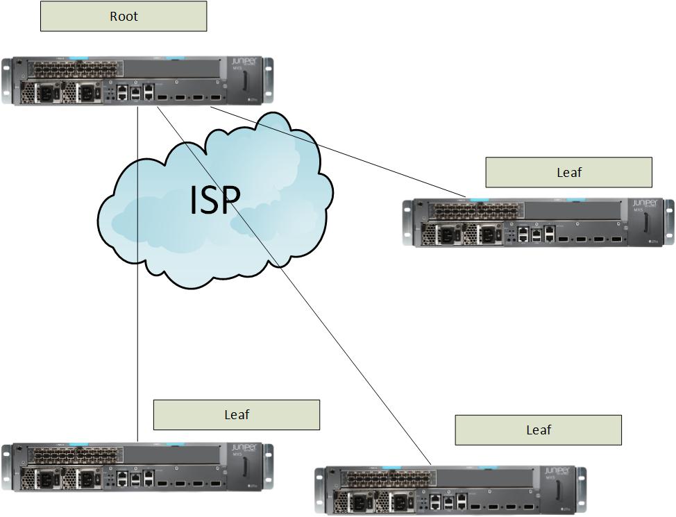
E-TREE because you have a Root and leaves.
again port based
or vlan based
They simplified the Layers here.
You have

IEEE
802.3 was the physical layer and datalink
802.1D/802.1Q is for VLANS
802.1ag is for fault management.
ITU uses
G series
Y series for OAM
MX series
MX80 = 80 gbps
MX240 =240 Gbps
MX480 = 480 Gbps
MX960 = 960 Gbps
MX5-MX80 can be upgraded using a license.
MX5 =20Gbps
MX10 = 40Gbps
MX20= 60Gbps
each MX number increase opens up either a MIC slot or 2 ports of 10GigE.
Bridging
the physical broadcast domain can be divided by 802.1D bridging.
Each bridge will have its own forwarding domain.
MACs are learned by the bridge using.
Learning
Forwarding
Flooding when you don't know where to go yet because it is not in the forwarding table
Filtering limits the traffic to the interfaces it chooses
Aging after X seconds it will remove it from the table.
global-mac-table-aging sets the timer on aging
Source MAC is the way it learns.
When it gets a packet it writes down where it came from (interface) and the MAC that sent it.
MAC TABLE
GE-0/0/1 0140.5505.2222
Once the above is on the table it will forward to it when needed.
If the destination is from the same port it came from then it drops it.
Because it assumes somebody else will send it.
Flooding is when you don't know where to go.
So you flood to all the interfaces except the one you got it from.
>show bridge mac-table
will show you the MACs
if they are static it will have an S you can manually add mac to the table ie STATIC
Each Bridging domain will have its own MAC table.
>clear bridge mac-table
drops all the dynamic addresses in the table and will flood again until it learns the MACs.
Switch ports operate either as access or trunk
Access connects to the VLAN
Trunk usually connects to another switch or the customer.
A trunk will have many VLANs.
native-vlan-id will take untagged traffic and trunk it to the other side which will reomve the native-vlan-id and send it untagged.
A TAG is 16 bits 802.1Q
Priority 802.1p is 3 bits
format is 1 bit by default 0
Unique Vlan is 12 bits.
#set bridge-domains vlan_name_100 vlan-id 100
the vlan number is 100 the name is arbitrary

The above just created the Vlans as you can see they are not attached yet to the any interface.
You set the VLAN on an interface.
set interface ge-0/0/1.0 family bridge interface-mode access
set interface ge-0/0/1.0 family bridge vlan-id 100

So in theory now server 1 can ping server 2 as they are on the same VLAN of 100
To configure a trunk
set interface xe-0/0/0 native-vlan-id 100
set interface xe-0/0/0 vlan-tagging
set interface xe-0/0/0 unit 0 family bridge interface-mode trunk
set interface xe-0/0/0 unit 0 family bridge vlan-id-list [100 200]

So let's say we have a packet in the CPU. The device looks at the VLAN and based on the VLAN + Mac table it will send it out of the correct interfaces. For example if we have a Vlan_100 tagged packet.
The device will send it out of GE-0/0/1 and Ge-0/0/0 as the packet is leaving the MX it will be stripped of the VLAN marking because this is an ACCESS port.
In the case of a TRUNK port which connects two switches, we want to keep that TAG of the VLAN.
So for example.
SRV01 will send a packet to SRV03.
The MX because it says that inteface ge-0/0/0 is Vlan_100 will use that TAG to decide where to flood it.
When the packet is flooded out a TRUNK.
The command vlan-tagging. Tells the router to ADD the TAG to the outgoing packet.
The second MX will receive the packet with the TAG vlan_100.
It will then send it to the interfaces that are Vlan_100.
So as the packet leaves for SRV03 the TAG is again stripped.
SRV01 and SRV03 are unaware of any vlan tags.
The vlan-id-list is optional
in this case it limits the trunk to the two vlans vlan_100 + vlan_200.
The last one is the mode trunk which tells the device this is a trunk interface and therefore
add the VLAN tag to outgoing packets.
If you have to make a list of VLANs for sepcific customers you can set up a list.
set bridge-domains sales vlan-id-list [10-12 20-22]

this adds a prefix to the Vlan so it will look like sales-vlan-xxxxxx #xx being the number of the vlan
>show bridge-domain
will show you the VLANs and their IDs along with the interfaces that can run them
>show bridge domain vlan_100 detail
will show you the MAC count of each VLAN
>show interfaces xe-0/0/0.0
will show you the link is up and if it has trunk-mode
If two VLANs have the same interface under them
that means that interface is trunking from VLAN to VLAN.
(not routing, just trunking)

>show bridge statistics
will show you number of MACs again.
Trunks forward broadcast.
So if you have Switches that do not have a specific VLAN
you can remove that VLAN from the trunk.

So you can for example.
Manually remove VLAN 10 from the trunk.
set interface xe-0/0/0 unit 0 family bridge vlan-id-list [100 200 10]
can be changed to
set interface xe-0/0/0 unit 0 family bridge vlan-id-list [100 200 ]
now the switch with red won't get VLAN 10 broadcasts.
MVRP can dynamically do this for you
instead of you manually having to do this.
802.1ak like ak47 because it shoots down unwanted broadcast.
Cisco has VTP and VTP version 2.
GVRP is now EOL end of life.
MVRP is the new version.
Cisco also support MVRP on some devices. Most IT guys know VTP courtesy of Cisco.
MVRP will send PDUs
The PDU will have an MRP message telling you which VLANS I have interfaces in.
MVRP has timers you can set.
mvrp {
join-timer milliseconds; #this will be how long to wait before broadcasting the vlans you have
leave-timer milliseconds; # this will be how long to wait before removing the vlan
if you get another vlan message then the vlan stays (keeaplive)
leaveall-timer milliseconds; I guess means leave all
MVRP timers (ms) Interface Join Leave LeaveAll ge-11/2/8 200 800 10000 ge-11/0/9 200 800 10000 ge-11/3/0 200 800 10000
set protocols mvrp no-dynamic-vlan this means that VTP or creation of VLANs on other switches
will not be done.
MVRP can copy vlan creation from one switch to another. Here we disabled this.
set protocols mvrp interface ge-0/0/4
this will turn on MVRP on the trunk interface ge-0/0/4
You can also set different timers per interface
>show mvrp
will show the status
will show if the dynamic-vlan creation is enabled
>show mvrp dynamic-vlan-membership
will show which ones were created dynamically assuming the dynamic-vlan is not set to no-dynamic-vlan
>show mvrp statistics
see stats on data movement.
IRB
an IRB integrated routing and bridging.
This means a L3 interface for the VLAN so the VLAN can get out and cross the wall
to reach another VLAN or IP.
This is the same as the Cisco SVI switches virtual interface.
This will be your gateway for the L2 hosts.
set interface ge-0/0/0.0 family bridge interface-mode access
set interface ge-0/0/0.0 family bridge vlan-id 300
ok the above is an access port .
set interface IRB unit 100 family inet address 172.16.0.1/24
the above is an interface IRB we give it a random unit and an IP.
We will now place this interface as the interface for the VLAN-id 300
set bridge-domains vlan_300 vlan-id 300
set bridge-domains vlan_300 routing-interface irb.300
to keep it nice and tidy try naming the irb unit with the same number as the vlan
in this case 300. (optional)
>show interfaces terse irb*
will show you the interface is up and the IP.
>show route
will show you the route to that pool
172.16.0.0/24 [direct] via irb.100
172.16.0.1/24 [local] via irb.100

Learning the MACs can be changed.
Per the device.
Per virtual switch which is a device in a device
Per the VLAN or Bridge-Domain
Per the interface.
timeout for aging is 300 seconds
MAC limit to learn
393215 per device
5120 per virtual switch
5120 per Vlan Bridge-domain
1024 per interface.
Up to a million MACs in Juniper MX.
You can also turn off mac learning.
Device set protocols l2-learning
per switch (virtual) set switch-options
per vlan/bridge-domain set bridge-domain Vlan_100 bridge-options
per interface set bridge-domain Vlan_100 bridge-options interface ge-0/0/0.0
You can change the MAC learning number
then if the table is full you can drop new items till the table empties.
set bridge domain vlan_100_bd bridge-options mac-table-size 4000
set bridge domain vlan_100_bd bridge-options mac-table-size packet-action drop
>show l2-learning global-information
will give you the details of what you have set up
>show l2-learning interface
will give you the details on an interface.
Filtering.
You might want to filter the port for whatever reason.
set firewall family bridge filter filter_name term term_001 from conditions
set firewall family bridge filter filter_name term term_001 then accept/discard
set firewall family bridge filter filter_name term term_001 then police/count
the last one is optional.
There is also an implicit discard at the end of the terms.
So if there was no match then they get dropped.
Application.
Apply to an interface
or to the whole bridge-domain/vlan
#set interface ge-0/0/0.0 family bridge filter input example_filter
#set bridge-domain vlan_300 forwarding-options filter input example_filter
Term Evaluation.
Single term - if there is a match it does the action . If not it hits the discard implicit
Multiple terms - if it matches a term it takes the action If not discard.
You can create a list of many filters . Up to 16.
then apply the filter-list
Virtual Switches.
Useful for splitting things.
One guy gets one and the other another. Then they don't see each others traffic.
routing-instance
virtual-router has a separate forwarding and a separate routing table.
default one is called default.
virtual-switch has a separate forwarding table MAC table VLAN ID space and spanning-tree domains
default-switch is the default one
default is inet.0 Layer 3
default-switch layer 2
show route will show you inet.0 and the Layer 3 and IRB interfaces.
show route forwarding-table will show you the PFE forwarding tables. L2
#set routing-instances VR1 instance-type virtual-router
for example on the router you can set up a NEW OSPF area 0
>show route table vr1.inet.0
Virtual Switch.
#set routing-instances Vswitch instance-type virtual-switch
#set routing-instances Vswitch bridge-domains vlan_100
notice how I have two VLAN 100 setup however each one is on a different Virtual Switch.
In order to configure interfaces and VLANs under it. specify the routing-instance always
#set routing-instances Vswitch interface ge-0/0/0.0
#set routing-instances Vswitch bridge-domains vlan_500 vlan-id 500
#set routing-instances Vswitch bridge-domains vlan_500 routing-interface irb.500
this will set up the Vlan under the correct Vswitch.
If you fail to mention the routing-instance the router assumes you want to add it
to default-switch.
show bridge-domain
will show you the "routing-instance' name the bridge-domains are under.
the IRB.500 we set up will show under the inet.0

to connect a Virtual Switch to a Virtual Switch you must use an external cable between ports
this is because the Spanning tree does not work as they both have the same MAC.
For connecting two routing-instances use a tunnel or a cable.
LT is a logical tunnel.
set chassis fpc1 pic0 tunnel-services bandwidth 1g
this turns on all tunneling and will create some
GR IP etc interface
We want the LT logical tunnel.
Provider bridging.
Vlans allow for 4096 12bits is the maximum.
Clients might have the SAME number Vlan .
So the ISP needs to provide for this scenario.
802.1ad
QinQ tunneling.
Allows you to have 4096 * 4096 options of routing items.

Also

The TPID will mark it as a S-VLAN
This is as best as I got it.
The book is terrible.

So my VLAN 100 C-VLAN goes on a Provider Edge Bridge.
The PEB Pushes a S-VLAN
The S-VLAN is used to reach my other site through many Provider bridges.
Then the PEB at site 2 pops out the S-VLAN and we are left with the C-Vlan which comes
out my customer edge port
OK
Push add an outer tag like the S-VLAN
pop remove the outer tag then we are left with the C-VLAN
swap swap the outer with another S-VLAN
pop-pop remove both so the packet wopuld be untagged
swap-swap
push-push add both
you get the idea. Pushing and Popping.
Ok,
So in QinQ the Mac table will get another field.
In this case push 200 will add the S-VLAN 200 to the packet.

During the travels


The action will be Pop the 200 so now we are back to the C-Vlan of 100
That way the simplistic view.
The configuration of a normal trunk is.

See how they differ,
The new way looks more intuitive and less typing.
So S-Vlan
Is for Shared Vlans
all of the VLANs will go with one OUTSIDE tag the 200

The new way looks more intuitive and less typing.
So S-Vlan
Is for Shared Vlans
all of the VLANs will go with one OUTSIDE tag the 200
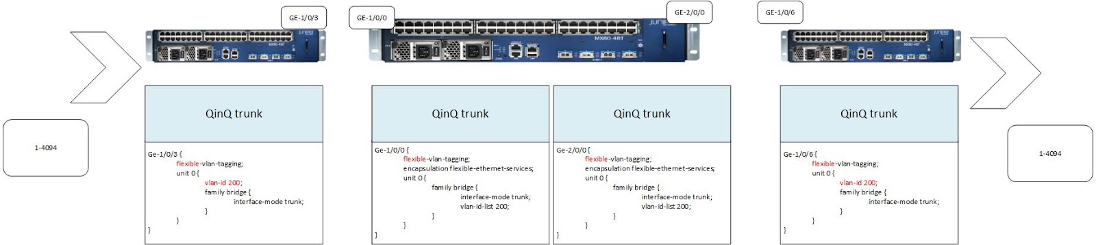
The C-VLAN
If you have an NNI network to Network Interface.
meaning one MAN/ISP needs to traverse another MAN/ISP002
meaning one MAN/ISP needs to traverse another MAN/ISP002
you can use the vlan-rewrite .
For example the other company treats you as a customer.
So vlan-rewrite translate 200 300
so translate 200 to 300
So vlan-rewrite translate 200 300
so translate 200 to 300
At the end of the route the PEB before you reach the customer they will pop out the 300 and we
are back to the C-VLAN of 100 which is the client.
are back to the C-VLAN of 100 which is the client.
>show interface ge-0/0/0.4
will show you the encapsulation and the Tag Actions.
So on the interface towards the C-VLAN it should say
Flags VLAN-tag [100] IN (push 200)
When it leaves towards the PB provider bridge it should say on that interface.
flags vlan-tag {200 100]
Okay the last part is a bit foggy.
The book has many typos.
Just remember with 4096 unique Vlans there is a limitation here.
So if you need more you have VPLS.
The book has many typos.
Just remember with 4096 unique Vlans there is a limitation here.
So if you need more you have VPLS.
Spanning-tree
STP 802.1D
Bridge ID = MAC + a Priority.
Root = the device with the lowest Priority
Root port = the port that leads to the Root
Desginated ports = the ports from the root to the Devices.
Desginated ports = the port from a device to the next one.
Desginated ports = the port from a device to the next one.
Root Path Cost = the cost to get to the root bridge.
Port cost = configurable 20000=GigE
On any device the port with the lowest Port Cost + Root path cost becomes the ROOT port.
BPDU will send the configuration.
TCN will notify there is a change it will go all the way to the Root and then the root
It does this by sending a TCN every 2 seconds.
will send back BPDUs once the device that sent TCN gets a BPDU it stops sending TCN
It does this by sending a TCN every 2 seconds.
will send back BPDUs once the device that sent TCN gets a BPDU it stops sending TCN
Port States
Block
Listen
learning MACs
forward DATA
If the ROOT ID and the Bridge ID in a bpdu match then you are the Root switch.
Port priority is 128
Hello is the time between BPDUIs
RSTP
provides faster convergence by marking ports as.
Edge ports- they are always in forwarding and do not change.
RSTP BPDU is sent every 2 seconds
3 failures and then it will consider it a failure.
Switches do not flush MACs from edge ports.
Only non-edge port changes create a TCN.
So more stable.
RSTP that gets an STP will use STP on that link
STP that gets RSTP drops them.
STP that gets RSTP drops them.
MSTP supports 64 spanning tree instances
VSTP supports up to 4094 Per Vlan Spanning Tree
Configuration
#set protocols rstp
#set protocols rstp bridge-priority 32k
#set protocols rstp max-age 20
#set protocols rstp hello-time 2
#set protocols rstp forward-delay 15
#set protocols rstp interface ge-0/0/0
#set protocols rstp force-version STP
the last one made this STP yes it is a stupid way of CLI-ing
#set protocols rstp
#set protocols rstp bridge-priority 32k
#set protocols rstp max-age 20
#set protocols rstp hello-time 2
#set protocols rstp forward-delay 15
#set protocols rstp interface ge-0/0/1
#set protocols rstp interface ge-0/0/1 priority 128 (default)
#set protocols rstp interface ge-0/0/1 mode point-to-point default for full duplex.
#set protocols rstp interface ge-0/0/1 mode shared # for half-duplex
#set protocols rstp interface ge-0/0/5 edge # access.
Now why they could make it go mode edge and keep it consistent I don't know.
>show spanning-tree bridge
>show spanning-tree interface
>show spanning-tree statistics interface
MSTP
MSTP allows you to configure regions.
So you can split the data traffic flow. This enables you to have the forwarding port block
So you can split the data traffic flow. This enables you to have the forwarding port block
and in the next msti the blocking port will forward.
This way you can use both ports.
Since you are paying for all the uplinks this load balances the spanning tree traffic.
This way you can use both ports.
Since you are paying for all the uplinks this load balances the spanning tree traffic.

The above is configuration-name region 1
revision level 1
You can have more Regions and each Region can have up to 16 MSTIs which are the colors.
show spanning-tree mstp configuration
MSTI 0 is also called the CST and is for compatibility with STP/RSTP.
This is how to use the CST to talk to STP/RSTP/VSTP

VSTP
allows you to configure a Spanning-tree for each VLAN you have.
Which if you have many Vlans becomes a pain in the ass and a drag on your CPU.
Port Priority default 128
Bridge Priority default 32
hell-time 2
forward-delay 15
max-age 20
point-to-point full duplex
mode shared ahalf-duplex
edge
cost 20000 default for 1 Gbps.
BPDU-protection
If you get a BPDU on an interface that is not supposed to have a switch.
You can tell the switch to disable the port
set protocols rstp bpdu-block-on-edge
this means that every port that is an edge port and gets a bpdu will block the port.
if you have a non-rstp switch . ie an STP one.
set protocols layer2-control bpdu-block interface ge-0/0/3 ge-0/3/4
this will set the same thing on those ports.
So when a bpdu comes the port will get blocked.
>clear error bpdu interface
will release the port.
Loop protection or Root protection.
Loop protection means the port is waiting for BPDUs if non arrive, even if they are crappy ones
then the port goes to inconsistent.
Root protection. If I know that on interface so and so the switches there should not become
a root, because they are low level switches or I set up a topology so the root is at the core.
I can set up the interface to never allow a BPDU coming from that interface to advertise
the switches as Root switches.
set protocols rstp interface ge-0/0/0 no-root-port
so now even if a switch on that interface says his priority is better I don't care and I block the port
The port will switch back to normal once I no longer get those BPDUs
OAM
Operations administration management
OAM should measure the following on a physical link.
Availability up or down
Frame Delay time to reach it in ms
Frame Delay Variation jitter
Frame loss dropping of packets

So F for Forward
B for Backward.
LoopBack - You start looping from the closest device to the next one
Once a loop fails you have reached the faulty item.

Linktrace is traceroute but for links.
LFM
Link Failure management
LFM client must be on the switch."
If the client is active, the client will look for a another client to bond with.
Only an Active client can send a LOOPback.
Loopback (intrusive)
Dying gasp before power down.
Critical event can be configured then the link will send a Critical alarm.
Link fault - is a simple signal loss
one OAM PDU every second.
It will be empty if you have nothing to say.
Possible actions.
Syslog the fact
Link down
Begin sending OAM PDU with the critical bit set.

Maintenance points
CFM message will linktrace

Ring
sub 50ms
RPL is a protocol for rings.

Basically once the ring is fine.
One port on A will be blocked.
It will send a keep alive on A to B to C to D to A
When there is a failure somewhere it won't get the keepalive
It will detect it as a failure.
Then it will re-enable the port so traffic can keep flowing from one device to the other.
The only difference is that now B has to go to A to D to C
where as before it went B to C
The failure take 50ms to detect.
The keepalive is called Ring Automatic Protection Switching message.
R-APS
A single VLAN will be dedicated for the R-APS message to travel along.
The RPL message says
no request
do not flush
RPL is blocked to signify all is fine.
In reality the process is more complicated but the explanations suck.
So use the above.
A#set protection-group ethernet-ring ring_name ring-protection-link-owner
will signify that A is the RPL master.
On the interface that you want blocked, ie A to D on A
A#set protection-group ethernet-ring ring_name east-interface ring-protection-link-end
this will tell the device that the East-interface is the one blocking.
now just add an interface.

A# set protection-group ethernet-ring ring_name east-interface control-channel ge-0/0/1.0
A# set protection-group ethernet-ring ring_name east-interface control-channel vlan 100
A#set protection-group ethernet-ring ring_name east-interface ring-protection-link-end
A# set protection-group ethernet-ring ring_name west-interface control-channel ge-0/0/5.0
A# set protection-group ethernet-ring ring_name west-interface control-channel vlan 100
in all the other devices just configure them as east and west. Again without the ring-protection-link-end
also without the ring-protection-link-owner
>show protection-group ethernet-ring aps
>show protection-group ethernet-ring aps detail
>show protection-group ethernet-ring interface ge-0/0/1.0
the output will tell you if it is forwarding or discarding.
>show protection-group ethernet-ring statistics
E voila.
You still have to BLock one iterface so it is costly however
you get sub 50ms conversion times. Which are great for a ring.
If you want to still have a quick path from A to D
you can set up another Ring similar to FDDI if you remember that piece of antique.
you get sub 50ms conversion times. Which are great for a ring.
If you want to still have a quick path from A to D
you can set up another Ring similar to FDDI if you remember that piece of antique.
Link Aggregation.
OK.
Your client is cheap and does not want to buy a 10 GigE switch.
So instead you can tell him for now to link aggregate several 1GigE
Your client is cheap and does not want to buy a 10 GigE switch.
So instead you can tell him for now to link aggregate several 1GigE
So he can build a 8* 1 GigE 8000 Mbps link.
The members of a link are called member interfaces.
If one fails, the other ones can still send data.
requirements
Member link speed and duplex must match
8 members is the maximum
an aggregated bundle is called an AE AE0 AE1 etc
Routing Engine traffic will use the lowest link
so GE-0/0/0 instead of GE-0/0/4
so GE-0/0/0 instead of GE-0/0/4
the load balancing algorithm uses L2 L3 or L4 data.
the load balancing for non-ip traffic uses L2 MAC SA and DA source and destination.
You can set up LACP
link aggregation control protocol.
This will monitor the links in the bundle.
One side must be ACTIVE lacp the other can be passive/active.
link aggregation control protocol.
This will monitor the links in the bundle.
One side must be ACTIVE lacp the other can be passive/active.

#set chassis aggregated-devices ethernet device-count 1
this sets up one AE
#set interface ge-0/0/3 gigether-options 802.3ad ae0
#set interface ge-0/0/4 gigether-options 802.3ad ae0
this adds both interfaces to the ae0
Now you can configure the ae0 like a normal interface.
#set ae0 unit 0 family bridge
#set ae0 aggregated-ether-options lacp active # this is optional if you want to turn on lacp
You can use the LAG also to make Layer 3 interfaces, in this case it was layer 2.
>show interfaces terse | match ae0
will show you the status of the interfaces up up
MC-LAG
Multi Chassis Lag.

Alright.
MX supports this.
MX supports this.
I didn't bother doing the LAG AE0
So the summary version is
This is what the configuration looks like
set chassis aggregated-devices ethernet device-count 1
set interfaces xe-0/0/44 ether-options 802.3ad ae1
set interfaces xe-0/0/12 unit 0 family ethernet-switching port-mode trunk
set interfaces xe-0/0/12 unit 0 family ethernet-switching vlan members v500
set interfaces ae1 aggregated-ether-options lacp active
set interfaces ae1 aggregated-ether-options lacp system-id 00:01:02:03:04:05
set interfaces ae1 aggregated-ether-options mc-ae mc-ae-id 3
set interfaces ae1 aggregated-ether-options mc-ae chassis-id 0
set interfaces ae1 aggregated-ether-options mc-ae mode active-active
set interfaces ae1 aggregated-ether-options mc-ae status-control active
set ae1 aggregated-ether-options mc-ae init-delay-time 240
set interfaces ae1 unit 0 family ethernet-switching port-mode trunk
set interfaces ae1 unit 0 family ethernet-switching vlan members v100
set interfaces vlan unit 500 family inet address 3.3.3.2/24
set vlans v100 vlan-id 100
set vlans v500 vlan-id 500
set vlans v500 l3-interface vlan.500
set protocols iccp local-ip-addr 3.3.3.2
set protocols iccp peer 3.3.3.1 session-establishment-hold-time 50
set protocols iccp peer 3.3.3.1 backup-liveness-detection backup-peer-ip 10.207.64.233
set protocols iccp peer 3.3.3.1 liveness-detection minimum-receive-interval 60
set protocols iccp peer 3.3.3.1 liveness-detection transmit-interval minimum-interval 60
set protocols rstp interface xe-0/0/12 disable
set multi-chassis multi-chassis-protection 3.3.3.1 interface ae0
http://www.juniper.net/techpubs/en_US/junos12.3/topics/example/multichassis-link-aggregation-qfx-series.html
the support depends on the platform.
In the appendix they describe the old syntax.
let's hope it's not on the test.
let's hope it's not on the test.
Alright.
On to MPLS.
My favorite subject
NOT!!!!
On to MPLS.
My favorite subject
NOT!!!!
Subscribe to:
Posts (Atom)