Static Routes.

Alright, this is the stape.
Network A wants to reach ISP B.
A static route will point the traffic.
set routing-options static route 0.0.0.0/0 next-hop 172.30.25.1
The result if you go for the Show Route table is.
root# run show route 192.168.63.14
0.0.0.0/0 *[Static/5] 01:09:00
> to 172.30.25.1 via fe-0/0/1.0
So basically.
On R1 there is a statement saying.
On R1 there is a statement saying.
anything 0.0.0.0 / any subnet 0 that comes along
There is a Static Route
So send it on the
Next-hop to 172.130.25.1
There is a Static Route
So send it on the
Next-hop to 172.130.25.1
Using Interface fe-0/0/1.0
Which is the IP of R2.
This is a static route, the negative about them is that if the link dies. The route will not work and
will not change until we MANUALLY change the route.
will not change until we MANUALLY change the route.
Now let's lab this nonsense.
You might go, oh well static route how hard can it be.
Well this is Juniper so let's see.
You might go, oh well static route how hard can it be.
Well this is Juniper so let's see.

Below is the configuration from the SRX.
root@srx101# show
## Last changed: 2013-02-08 20:05:17 UTC
version 12.1R1.9;
system {
host-name srx101;
root-authentication {
encrypted-password "$1$3P3agxZe$Pmrwg9xRcH73xJDpeCrGM0"; ## SECRET-DATA
}
}
interfaces {
fe-0/0/1 {
unit 0 {
family inet {
address 10.0.0.1/30; # this will connect to the other SRX
}
}
}
fe-0/0/2 {
unit 0 {
family inet {
address 10.0.0.5/30; # this will connect to the other SRX
}
}
}
fe-0/0/6 {
unit 0 {
family inet {
address 192.168.1.1/24; # this is the interface to the LAN
}
}
}
}
security {
forwarding-options {
family {
mpls {
mode packet-based; #this makes the SRX behave like a cheap router
}
}
}
}
The other one is identical minus the IP changes.
Ok.
Now assuming on WAN router you set up/
Now assuming on WAN router you set up/
route 0.0.0.0 0.0.0.0 192.168.0.1
which is the Cisco gateway in my case.
Or you set up a default gateway if you are using a PC.
Or you set up a default gateway if you are using a PC.
You should be able to ping.
192.168.0.1 which is the Interface 0/7 on the SRX>
You should be able to ping the
You should be able to ping the
10.0.0.2 which is the IP on the interface 0/1 on the SRX.
This is simply because the SRX 999 should have the routes to those two in the routing table.
Let's have a look at the Routing Table on the SRX999.
root@999# run show route
inet.0: 6 destinations, 6 routes (6 active, 0 holddown, 0 hidden)
+ = Active Route, - = Last Active, * = Both
10.0.0.0/30 *[Direct/0] 00:10:40
> via fe-0/0/1.0
10.0.0.2/32 *[Local/0] 00:10:40
Local via fe-0/0/1.0
10.0.0.4/30 *[Direct/0] 00:10:40
> via fe-0/0/2.0
10.0.0.6/32 *[Local/0] 00:10:40
Local via fe-0/0/2.0
192.168.0.0/24 *[Direct/0] 00:37:15
> via fe-0/0/7.0
192.168.0.1/32 *[Local/0] 00:37:15
Local via fe-0/0/7.0
I marked in GREEN the interfaces we just configured on the SRX.
Notice how the table is not the prettiest.
However it states,
Notice how the table is not the prettiest.
However it states,
if I want to send 192.168.0.0 with a subnet of 255.255.255.0 I will send it DIRECT Via
interface -0/0/7.0
interface -0/0/7.0
Ok. Now let's add a static route.
If you want to send something to 192.168.1.0/24 then send it using the 10.0.0.1 IP to SRX101 who should forward it on to the LAN router. and eventually reach the 192.168.1.2 IP.
So
root@999# show routing-options
static {
route 192.168.1.0/24 next-hop 10.0.0.1;
}
The command is set routing-options static route 192.168.1.0/24 next-hop 10.0.0.1
Normally if you are starting from scratch this will still not enable you to ping 192.168.1.1
or even the next hop 10.0.0.1 from your WAN router.
Simply because the SRX101 does not know how to return the response packet.
or even the next hop 10.0.0.1 from your WAN router.
Simply because the SRX101 does not know how to return the response packet.
So on SRX101 we have to place a static route to route the response back.
I used the static route 0.0.0.0/0 which means ALL IPs that are there , their next-hop is 10.0.0.2
root@srx101# show routing-options
static {
route 0.0.0.0/0 next-hop 10.0.0.2;
}
Alright, so on the table we finally have the routing table with a static route.
[edit]
root@srx101# run show route
inet.0: 7 destinations, 7 routes (7 active, 0 holddown, 0 hidden)
+ = Active Route, - = Last Active, * = Both
0.0.0.0/0 *[Static/5] 00:16:31
> to 10.0.0.2 via fe-0/0/1.0
10.0.0.0/30 *[Direct/0] 00:33:53
> via fe-0/0/1.0
You can clearly tell the Juniper book writers are too experienced and love throwing terms.
Next-Hop is typically the IP address of a directly connected device.
you can also send the next-hop to the bit bucket.
Which means to drop it.
There are two ways.
Reject will send an ICMP unreachable.
Discard will drop it without any message.
Static routes stay in the routing table until they become inactive.
When the next hop is unavailable it will become inactive.
Default Static hop is 5.
So if we want to set up TWO static routes.
We will leave one as the default and then add another one with a higher Metric.
In choosing the next hop the lower the Priority in the Routing table
The more likely it will be chosen.
So
route 0.0.0.0/0 {next-hop 10.0.0.2;qualified-next-hop 10.10.10.6 {preference 10;}
So the next-hop 10.0.0.2 has the default of 5
the next-hop 10.0.0.6 has a priority of 10
So 10.0.0.2 will be chosen.
Now if it goes inactive because we unplugged the cable from Fe-0/0/1
Then the 10.0.0.6 will be chosen .
Some more things you can do are.
static {
defaults {
preference 200;
}
the above for example will set any static route to have a low priority of 200 instead
of the usual 5.
static {
route 172.16.0.0/24
next-hop 10.0.0.5;
no-readvertise
}
So this for example will NOT advertise that route to the routing protocols
They recommend using this for management networks.
IPV6 default route.
set routing-options rib inet6.0 static route 0::/0 next-hop 3001::1 preference 250
Tables.
The Routing table is called RIB.
So IPv4 has a RIB
IPv6 has another RIB.
So when you want to set up an IPv6 route you have to reference THAT RIB.
which is what we did above.
Shitty writing.
Ok.
Besides changing the "preference"
you have another option.
If two routes have the SAME preference
like
route 0.0.0.0/0 next-hop 10.0.0.1
route 0.0.0.0/0 next-hop 20.0.0.1
they would both have the same preference.
So you can use the METRIC.
The same rules apply, the lower the metric. Then that will be chosen.
This is from Cisco as Juniper can't bother explaining the theme.
How Metrics Determine the Route Selection Process
Routes are chosen and built in the routing table based on the routing protocol's administrative distance. The routes learned from the routing protocol with the lowest administrative distance are installed in the routing table. If there are multiple paths to the same destination from a single routing protocol, then the multiple paths would have the same administrative distance and the best path is selected based on the metrics. Metrics are values associated with specific routes, ranking them from most preferred to least preferred. The parameters used to determine the metrics differ for different routing protocols. The path with the lowest metric is selected as the optimal path and installed in the routing table. If there are multiple paths to the same destination with equal metrics, load balancing is done on these equal cost paths. For more information on load balancing see
can
So
{master:0}[edit]
lab@exA-1# show routing-options
static {
route 0.0.0.0/0 {
next-hop 10.0.0.1;
qualified-next-hop 50.0.0.1 {
metric 100;
}
metric 50;
}
}
Alright.
So two routes 0.0.0.0/0 next-hop 10.0.0.1 metric 50
So two routes 0.0.0.0/0 next-hop 10.0.0.1 metric 50
routes 0.0.0.0/0 qualified-next-hop 50.0.0.1 metric 100
If you don't use the qualified-next-hop it will not work.
the qualified-next-hop let's you specify "different" metrics and preferences.
F$%k me, that was Static routes. Was supposed to be simple.
Aggregate routes
So
So

Alright.
Now if you export each route to the ISP router
The ISP router will have the following routing table.
The ISP router will have the following routing table.
192.168.0.0/24 next hop ACME
192.168.1.0/24 next-hop ACME
192.168.2.0/24 next-hop ACME
192.168.2.0/24 next-hop ACME
Each route will take a 1KB of memory on that router.
the rule of thumb seems to be.
512 MB (default) DRAM, upgradable to 1 GBsays
• Supports routing tables with up to 1 million entries
So I would estimate that each
1 "GB" = 1,048,576 "KB"
So Each entry will take a KB
Now if you want to make the table on the ISP router smaller and you can assume that all of the 192.168.0.0/16
go out the interface towards ACME.
You can then use an aggregate.
ACME router will publish an AGGREGATE route.
go out the interface towards ACME.
You can then use an aggregate.
ACME router will publish an AGGREGATE route.
the route will say.
192.168.0.0/16 next-hop ACME router
So the ISP routing table will say
0.0.0.0/0 next-hop internet
192.168.0.0/16 next-hop is ACME.
Route Summarization and Route Aggregation appear to be the same thing.
Don't you love the different naming. NOT.
Don't you love the different naming. NOT.
So on router ACME
set routing-options aggregate route 192.168.0.0/16
this sets up the aggregated route.
then you have to
Set policy-options policy-statement aggregate-into-rip term first-term from protocol aggregate then accept;
Set protocols rip export aggregate-into-rip
So basically we created the Aggregate and then told the RIP protocol to export that aggregate to other
RIP parties.
RIP parties.
If you are still in static land.
Simply go to ISP router and add.
Simply go to ISP router and add.
set routing-options static route 192.168.0.0/16 next-hop ACME
so as you can see,
You can aggregate either using the static
or when you are using routing protocols you can aggregate routes and then export them.
You can aggregate either using the static
or when you are using routing protocols you can aggregate routes and then export them.
OK.
Now
192.168.0.0/16 covers a lot of networks.
What happens if the ISP sends a 192.168.90.0 packet towards you.
What happens if the ISP sends a 192.168.90.0 packet towards you.
The DEFAULT is to REJECT.
ie send ICMP unreachable.
ie send ICMP unreachable.
You can change that and make that a DISCARD. Which will drop it silently.
Up to you.
Default Value of an aggregate route is 130 so you can change the preference you are exporting.
on the router you can type
>show route 192.168.0.0/16 exact detail
and you can see the details about the aggregate and the contributing routes
you can also see if the next-hop is reject in case of not finding the said networks.
you can also see if the next-hop is reject in case of not finding the said networks.
Seriously the person that wrote this first chapter deserves some ##$#$#%%#
Not to mention the Examples on Juniper website are about as easy
to get as nuclear bomb building from wikipedia.
to get as nuclear bomb building from wikipedia.
Generated Routes
OK,. I mean the explanations on google are atrocious.
I mean they are about as bad as a virgin telling you what to do with a woman.
I mean they are about as bad as a virgin telling you what to do with a woman.
I'll get back to this after I lab this.
martian Addresses
OK, martian addresses = addresses that will not be added to the routing table.
0.0.0.0/8
127.0.0.0/8 # which is the loopack
128.0.0.0/16 # this is a flaw as RIPE has allocated these IPs to public people
191.255.0.0/16 # same thing another flaw. Apparentley Juniper used them for some internal items.
192.0.0.0/24 god knows why.
223.255.255.0/24 or longer
240.0.0.0/4 or longer.
You can add more to the MARTIANS or drop some
show routing-options martians
anyway to be honest this whole Martian thing is a bit sketchy.
Just so you know it goes.
set routing-options martians 23.0.0.0/8 or longer
this will drop all 23.0.0.0/8 from any routing table.
Routing Instances.
OK.
You can set up many "routing instances"
Each one will have its own.
OK.
You can set up many "routing instances"
Each one will have its own.
1. Routing table
2. Interfaces
3. and routing protocols.
The software JUNOS will keep them apart.
That way you can accomodate many clients or different scenarion.
That way you can accomodate many clients or different scenarion.
The master one is called INET.0
lab@exA-1# run show route instance
Instance Type
Primary RIB Active/holddown/hidden
master forwarding
inet.0 2/0/0
Notice how the table is extremely well aranged. A la DOS from 1995
The Instance is MASTER
The primary RIB Routing Information base is inet.0
the active/holddown/hidden will give you the details of how many routes you have
So 2 are active - non on holddown - non hidden.
This is the Google Explanation
""Routes in holddown state are in pending state before declared inactive. Hidden routes are not in the routing table because of a routing policy.""
I mean come on.
Does everybody just copy paste and blog.
I guess I must be dumb.
Maybe I will download Junos for dummies.
Research the holddown and hidden.
I'll ask the Juniper guys, they'll probably quote me the same thing as above.
Ok,
This is an example of creating ANOTHER router.
This is a virtual router.
It will have its own routing .
Its own default gateway
and its own OSPF process.
{master:0}[edit]
lab@exA-1# show routing-instances
Routing2 {
instance-type virtual-router;
interface ge-0/0/0.0; ## '
interface ge-0/0/1.0; ## '
routing-options {
static {
route 0.0.0.0/0 next-hop 10.0.0.2;
}
}
protocols {
ospf {
area 0.0.0.0 {
interface ge-0/0/0.0;
interface ge-0/0/1.0;
}
}
}
}
So the type is vritual-router
it has interface 0 and 1
a static route
and its own OSPF.
When you ping the address you can reference the INSTANCE to use for the IP resolution.
chapter 3
Loadbalancing and filter based forwarding.
OK.
load balancing.
I am paying for 2 links to another guy. I want to loadbalance and use both.

So I can load balance by packet.
However
If I send A B C D
They might arrive as
A D C B
So the other device has to waste time waiting around for them to come.
So it can arrange them into the correct flow of
ACBD which is let's say a phone conversation.
So instead of load balancing by packet.
I can load balance by FLOW.
same source - same destination - same protocol will be considered a single flow.
By default. Junos selects ONE route to use.
So how to control the three options.
set policy-options policy-statement load-balance-all then load-balance per packet
Set policy-options policy statement load-balance-some
from route-filter 10.0.0.0/24 exact
from route-filter 11.0.0.0/24 exact
THEN
load-balancer per packet.
notice how everything says PER-PACKET
however newer platforms will use the flow
older ones will actually do this per-packet. packet.
god , can't you update the command ???
Applying it works
set routing-options forwarding-table export policy "load-balance-some"
now as you can see the forwarding table will export into itself the load-balancing.
So far not the best as far as applied logic.
set forwarding-options hash-key family ineet layer-3 layer-4
the above will set up the forwarding to include also the layer 4 information of ports
when separating flows to forward.
show route forwarding-table
will show you the routing forward table and in it you will have the two next-hops
filter based forwarding.

Ok, Let's say I am a service provider and I am paying two ISPs
ISP A gives me a low latency fast link
ISP B is some bad ISP.
Now I can give my client two options.
Client 10.0.0.0 wants to use ISP A
client 20.0.0.0 wants to use ISP B.
So to separate the traffic I can use a FILTER based Forwarding.
I will create a FILTER based on the source address.
set firewall family inet filter Separate_the_two_clients term term_01 from 10.0.0.0/24
set firewall family inet filter Separate_the_two_clients term term_01 THEN routing-instance ISPA
same thing but for the other client
set firewall family inet filter Separate_the_two_clients term term_02 from 20.0.0.0/24
set firewall family inet filter Separate_the_two_clients term term_02 THEN routing-instance ISPB
so the "firewall filter " Separate_the_two_clients has two terms.
Term01 sends the guys from 10.0.0.0 to ISPA
Term02 sends the guys from the 20.0.0.0 to ISPB.
Now you apply this Filter on the INTERFACE that connects to the two clients as an INPUT.

So GE-0/0/5 will have an input filter that will separate the packet flows
So client 1 goes to routing-instance ISPA
So Client 2 goes to routing-instance ISPB
Now you have to create the routing-instance
Each routing-instance will use a different ISP destination IP.
So
set routing-instances ISPA instance-type forwarding routing-options static route 0.0.0.0/0 next-hop IP_ISPA
set routing-instances ISPB instance-type forwarding routing-options static route 0.0.0.0/0 next-hop IP_ISPB
now in the past we created a separate routing-instance that was a virtual-router
here we can simplify it by creating a routing-instance that is a forwarding one because we are
only looking to forward here, not do full routing.
Now we apply the FILTER to the interface.
set interface ge-0/0/5.0 family inet filter input Separate_the_two_clients
set interface ge-0/0/5.0 family inet address 10.0.0.1/24
set interface ge-0/0/5.0 family inet address 20.0.0.1/24
so the inteface has the two IPs from the subnets.
It has also been applied the FILTER.
Now
In order to get the ability to route to the next destinations aka ISPA and ISPB
we need to add the instances to the RIB inet.0
set routing-options interfaec-routes rib-group inet my-rib-group
set routing-options rib-groups my-rib-group import-rib inet.0 ISPA.inet.0 ISP.inet.0
so now all the tables can use each other.
So now the ISPA.inet.o can see the other interfaces.
So can ISPB.inet.0 can see the routes from inet.0 too
So now both know how to route to the next-hop
OK, as if that wasn't easy.
I can just feel myself clamoring for some RIBs with a barbecue sauce.
There is another way of doing this.

Ok,
I don't care what the RIBs do we can use TOPOLOGY.
set routing-options topologies family inet topology Video_top
so you call up topolgies and give it a name video_top.
You create a FILTER as usual
set firewall family inet filter My_Firewall_filter term 01 from forwarding-class expedited-forwarding
the assumption here is that the video will have a QoS expedited-forwarding on it.
then topology Video_top
so the Firewall Filter is set
It will be applied to the interface.
set interface ge-0/0/5.0 family inet filter input My_firewall_filter
so in comes traffic it is video and has expedited-forwarding the filter sends it to topology Video_top.
Each topology you create automatically populates it with routes from the default table.
So there is a new ROUTING table with the routes from the DEFAULT table.
Chapter 4 OSPF.
Well at least we don't have EIGRP here. So can't complain.
OK, OSPF floods LSA link state Advertisments
The Djikstra algorithm will calculate all the LSAs and come up with the shortest path.
Open Short Path First.
All of the LSAs are in the LSDB Link state Database.
Advertising ID his links and the COST
In the same AREA each router will have the same LSDB.
Once the calculation is done, then the device will add that route to the routing table.
OSPF has a few packet types. They are.
Type 1 Hello - The Hello will set up a relationship.
Type 2 Database description will describe the Database it has.
Type 3 link-state request will request a route
Type 4 link-state update will provide that route
Type 5 link-state acknowledgement will ack that I got the route.
Type 1 Hello.
Hello is sent using Multicast 224.0.0.5
Each router sends Hellos.
In order for the Hello's to be worthwhile.
You need to form an adjacency.
So every 10 seconds you get a Hello. Unless this is a Non-Broadcast interface then it is 30 seconds(ATm,FrameRelay)
the Hello looks like this.

The network mask is for Broadcast to agree on a network.
The hello INTERVAL is 10 seconds in Juniper 15 in Cisco so make sure it matches.
The Dead interval is 4 times the INTERVAL. So if the interval won't match this won't match either.
After the 4*10 seconds are done, the relationship is dead .
Options allows you to set up Stubs and similar so they should match.
Router Priority is for selecting the Designated Router. 0 zero means it will not participate.
Designated router will handle all the router to router updates. So you won't have to update all the routers.
this will tell you who is the DR. if it is 0..0.0.0 then none has been selected.
Backup designated router will take over if the Desginated router does not work.
if none is selected you get 0.0.0.0
Neighbor ?? will have the ROUTER ID of every neighbor I have seen.
Alright, that was an Hello.
Based on the hello you just got you can become neighbors
You can also select a DR and a BDR.
Type 2 Database Description
Alright DD
Database Description.
The two routers who just became neighbors. Need to decide on the update.
The one with the higher RID will become the MASTER and the other guy the SLAVE
After this they can exchange LSAs.
So they quickly send I have 20 entries then other guy goes I have ten.
Type 3 Link State request
Sending the entries or LSAs
So now each entry from the table can be requested.
Send me entry 5 and 10
type 4 Link State Update
So now it will send the update .
OSPF header number of advertisements and the LSAs
type 5 link state acknowledge
so now you can ACK that you got them.
It is an OSPF packet with the list of LSA headers I got.
Forming the adjacency.

Adjacency optimization
OK.

Normally if the OSPF will run and start setting up adjacencies.
That is what will happen. Each device will be a BFF neighbor with the other devices.
This will create a lot of gossip or network chatter.
So they came up with the concept of
BDR and DR
The DR is the designated Router it will be the one that holds all the updates and updates everyone.

So in this case the DR now updates everybody.
The rest of the switches will only reach the 2-way stage of communication between each other.
The same thing happens with the BDR.
They will link to it, however it will not be sending any updates on the wire.
The above is only relevant for broadcast medium.
Where the Multicast 224.0.0.1 would work.
If the link is a POINT to POINT there is no need for the DR/ BDR election process.
set protocols OSPF area 0.0.0.0 interface ge-1/0/0.0 interface-type p2p
>Show ospf interface
also on a p2p link the link will not generate LSA type2 data.
Elections for presidient
OSPF has a DR election priority of 128
The higher the Priority the more chances of you getting elected.
If priority is the same higher RID will win the election.
Existing DR will not be replaced.
>show OSPF neighbor.
DR and BDR will have a state of FULL.
all of the "other" ones will have a state of 2way between themselves.
Areas

Ok,
To allow scalability, you can divide the network routing updates into areas.
The Routers that have legs in two areas or more will be able to summarize the areas.
The LSDB for each area will be a lot smaller.
So for example in the above instead of having LSDB 0 = 500 MB
now we have LSDB5 = 5MB LSDB6 = 5MB LSDB0 = x etc
This allows you to use smaller routers with less memory and be able to limit
LSA flooding that happens every tim there is a change.
For example. If AREA 6 router have a change. It will only have to update the router on Area5/6/0 border.
ABR is an area border router- basically any router that connects two areas is an ABR
ASBR is a Autonomous system boundary router - Any router that sits between OSPF and non-OSPF
networks .

These are the type of updates will move from one area to another.

Alright
Now a totally stubby area will only get a default route injected into it.
That will be send all to backbone.
0.0.0.0/0 next-hop IP of backbone
A Stub has some devices that need to send intra area to each other.
A not so stubby area is an area that has an ASBR to the outside.
The rest is the normal areas or a backbone.
LSA 1 is hi this is me and these are my interfaces
LSA 2 is for the BDR/ DR They send them describing the network to the non-bdr/DR guys
LSA 3 is a summary of this area this summary is sent to the other area. An ABR will generate it.
LSA 4 is the ABR sending details about how to reach the ASBR routers in his area.
LSA 5 External is from the ASBR giving you the network details of the external network.
LSA 7 NSSA external is from the ASBR to all his guys in the NSSA. The ABR will convert this to LSA5 to
send it to the other areas.
OSPF v2 is for IPv4
OSPFv3 is for both IPv4 and IPv6
Authentication
Simple
MD5
IPSEC
ABRs can summarize.
prefix-export-limit #limits the number of prefixes that will be exported to OSPF.
Graceful restart will notify the other devices you are restarting
BFD bidirectional forwarding helps to quickly tell link failures.
Setting it up.
set protocols OSPF area x.x.x.x interface ge-0/0/5.0
or
set protocols OSPF3 area x.x.x.x interface ge-0/0/5.0
Set routing-options router-id 192.168.0.1
marks for you the name of the router that will appear on the advertisements.
If not it will use the first interface like loopback.
If not loopback then the first hardware interface.
best practices is to always set up the RID.
OK.
Some exciting labs.

Pretty much the set up is the setup above.
This is what an OSPF configuration looks like on a Junos.
protocols {
ospf {
area 0.0.0.0 {
interface fe-0/0/1.0;
interface fe-0/0/2.0 {
metric 100;
}
}
area 0.0.0.2 {
interface fe-0/0/7.0;
}
}
So Area 0 is interfaces 1 and 2 with a METRIC of 100 for 2.
So Area 2 is interface fe7
If you match it on the other router, they will easily for an adjacency.
root@999# run show ospf neighbor
Address Interface State ID Pri Dead
10.0.0.1 fe-0/0/1.0 Full 33.33.33.2 128 35
10.0.0.5 fe-0/0/2.0 Full 33.33.33.2 128 37
192.168.0.2 fe-0/0/7.0 Full 33.33.33.10 1 34
Alright.
Address is the IP address of the neighbor
Interface is which interface do I use to reach him.
Address is the IP address of the neighbor
Interface is which interface do I use to reach him.
State FULL , means they have both synchronized the LSDB databases
ID is the "router-id" you can configure on each router.
PRI is the priority for becoming a DR or BDR.
Dead is how many seconds before the neighbor is dead. This will constantly change every hello.
run show ospf statistics will give you some stats.
Troubleshooting.
run show ospf database
will give you the details of the routes in the LSDB

Alright.
Area 0.0.0.0 = 0
Router is the * me 33.33.33.1 would be the router-id of the router this printout came from.
the second "Router" is the 33.33.33.2 which is the other SRX in my Lab
In Area 0.0.0.1
The second router is the WAN one 33.33.33.10
The second router is the WAN one 33.33.33.10
BGP
AS is a set of routers operating under the same administration.
NLRI network layer Reach-ability information - this is the LSDB for the BGP. a database of reachable-ness.

Communication from one AS to another AS is eBGP external.
communication internally in the AS can be iBGP internal
The TTL by default of eBGP is 1.
So devices should be connected directly to each other.
SO ASN1 speaker should connect directly to ASN2 speaker.
If the connection is further than one hop, you need to create a "Multi-hop" eGBP.
iBGP uses the loopback interfaces on routers as they do not change.
iBGP relies on an IGP like OSPF to travel on.

BGP is manual, there is no auto discovery.
You have to manually tell him who his buddies are and what is their ASN.
BGP relies on PROTOCOL TCP port 179
so TCP must be alive and doing well for bgp to work.

Sorry for the size, hard to put so much information into a diagram.
Print this out and work on it.
There are SIX states. The States will give you a hint on where the process has failed.
First off is IDLE.
IDLE is a failure, when things fail they all go back to IDLE and from there will restart the process again.
So from IDLE you configure "manually" the BGP settings and the router will start sending TCP
because BGP is over TCP port 179 to the neighbor AS.
So for example.
This is what a CIsco BGP command looks like
Router007#
router bgp 100
neighbor 129.213.1.1 remote-as 200
c the ASN of router 007 will be 100
the neighbors IP address is 129.213.1.1 and his ASN is 200
So now from IDLE your router goes.
Open a TCP connection    using 179   to    129.213.1.1.
### so if port 179 is closed   or you don't have any ports available higher than 1023
remember a connection looks like    from  1023  to  port   179
and the response will be   from 179  to port 1023
## so if no ports are available or you cannot route to 129   the
{{CONNECT state}}   will fail.  If it fails it goes back to IDLE
Let's say you have port 179 and all is good.
The Router will send a message to OPEN  the processes on the router
the message is  OpenMessage.
Since this is TCP it will get a confirmation an ack  that the OpenMessage was received.
If the confirmation comes.
It switches to    OPENSENT state
if it fails , it will switch to ACTIVE from ACTIVE it will try one more time. If it fails again, then it goes to IDLE.
So ACTIVE, will try one more time and if it fails drop it and go back to IDLE.
OPENSENT   means I sent an Open.
Now I just wait for the other device. That was ALSO manually configured to reach the same STATE and send me an OpenMEssage.
The other device will have the similar manual configuration.
Router111#router bgp 200neighbor 11.11.12.12 remote-as 100So once both devices have sent each other the OpenMessage. They will switch to OpenConfirm and will trade KeepAlives.Once the KeepAlives are flowing. They can switch to ESTABLISHED and trade updates+keeaplives all the time.A NOTIFICATION is sent to the peer when the keepalive timer has run out. You send a NOTIFICATION and switch automatically to IDLE.OK, 6 States.IDLE - not goodActive - not good but will give it one more try.Connect - is on the way. OpenSent and Openconfirm should go by quickly if all is well.Established - GREAT!!!!!!!So once TCP three way shake was good. You will send an Open Message.The message starts the actual BGPUpdate will trade BGP routing infoKeepalive do not have any data , only a header.Notification means the BGP session has had a malfunction - drop and go back to idle give me 10 pushups.Refresh - you don't readvertise routes. however you might want to "refresh" the routes you have so you get a refreshing coke.If a neighbor goes down all the routes that came from that neighbor are deleted.Using the BGP attributes you can detect LoopsA BGP update is a path and the prefixes that can be reached using this path.Let's see.Alright,this is a normal flow of a BGP.Customer A gets a pool of IPs. His ISP will aggregate them into it's own ISP pool. His ISP will publish the ISP pool to the Internet.So now Customer B, does not need a "specific" line for 192.168.0.0/24 It just needs a line for the much larger pool of 192.168.0.0/16This allows you to save the number of lines in the BGP tables. Currently there are 300000 to 400000 routes in BGP.OK Now. in BGP you can Dual home.Dual Home = connect to two or more ISP providers each with a different ASN.So now Customer B has TWO routes to reach customer A.BOTH will be in the BGP table. The Selected route will be the Shorter one of the two, that route will go to the ROUTING TABLE.The select route is called the "best route "On BGP packets that go along you can add Attributes. Those Attributes allow BGP a fleixble complicated system of route choice.The Common Attributes are.The book here sucks big time and the explanations are about as good a Halal hot dog stand in NY.Next- HopAlright. AS 6431 is sending an update the update will say.To reach meMe being 135.207.0.0/16 Please add to your table that the NEXT-HOP must be my router 12.125.133.90So nowThe BGP table in AS7018 will say.12.125.133.90 AS PATH AS 6431The Routing table in AS7018 will say.Route 135.207.0.0/16 next-hop 12.125.133.90OK, the BGP update keeps travelling. So now AS 7018 replaces the Next-hop with the next-hop of its own router. Then it adds the AS7018 to the AS PATHSo now The BGP table on AS12654 will say.12.127.0.121 AS PATH 7018 AS 6431The routing table will say.Route 135.207.0.0/16 next-hop 12.127.0.121So, as the great explanation by Ljiljana Trajkovic from http://www2.ensc.sfu.ca/~ljilja/cnl/ states. Every time you cross an AS the next-hop will change and the AS number will be added to the AS PATH.OK, AS path we talked about this in the BGP Dual home slide and here. Everytime you cross an AS the AS is added to the AS-PATH .If the AS-PATH appears twice, then that means you have a LOOP So that route will be dropped.OK. AS - path easyNext-hop easy.Origin.


Ok.
Based on this
http://www.juniper.net/techpubs/en_US/junose10.0/information-products/topic-collections/swconfig-bgp-mpls/understanding-the-origin-attribute.html
The Origin will say where the route came from.
If it is a BGP route.
For example you have the BGP router  Network command.
The route will say Origin I for IGP or (0)
If it is from the protocol that was a predecessor to BGP
it was called EGP  it is from 2000 back when I started IT.
Then it will say.
E for EGP (1)
If the route says incomplete.
That is ok too.
It just means it came from a static route.
Or you used a "redistribute" command to add it from a interior gateway protocol.
For example
In this case we redistributed the STATIC into the BGP.
The default is I for (o) IGP.
This is a bit misleading as IGP sounds like an IGP like OSPF or ISIS
and the EGP  sounds like EBGP.
So sucks to be us.
Alright so Next-hop will point to the router who sent the update.
AS path will show the path to follow
Origin will say if it came from BGP or was injected into the BGP using redistribute.
Now

Let's try.
Local Preference.

The Local Preference is used within the AS.
If the Local preference of a router is higher.
The router next to the Firewall will use the Local Preference 300 as his exit.
Once the packet leaves the AS the local preference is deleted/removed.
This is a well-known discretionary attribute. If you want you have the discretion to use it.
Ok.
WE know which way to get the data out = local preference
When we send updates we place the next-hop as our router  and every ASN will change it to their routers IP
When people get our updates they can see the AS path they have to take to reach us
When people get the update they know if it is a BGP route or it was redistributed.

I forgot BGP routes are preferred to the Incomplete ones.
OKay
MED
Multiple Exit Discriminator.

Okay.Let's say we have two ISPs one is cable so the download is cheap and easy. The other is a T1 which is expensive.Now you can advertise WHICH route do you want people to take.You do that by adding a MEDThe MED by default is ZERO and not every AS supports this.So in the above example. We set up the MED to be 10 on the cheap ISP and MED 30 on the expensive one. So now. Traffic coming back from the AS 65005 will take the Cheap ISP route because the MED number was lower.Notice how most things the higher the number the more likely it will take it, like the Local Preference. In this case it is the OPPOSITE. The LOWER the number the more chance that will be taken.the MED will also be removed by the ASN when it sends the update to the next ASN It is an "optional nontransitive" attribute. So it does not transit.
Community.
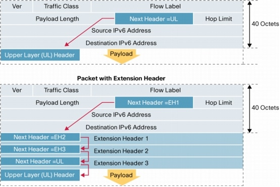
Community is an added number to the ASN for example 65001:133You can use that number with the ISP that agree on using communities to control the traffic flow or distribution. The community number is arbitrary or agreed upon by RIRs.For example. I might have many clients in an ISP but I don't want to export all of their routes. So I can have them add the No-Export or the no-advertise. No-Export means do not export to any EBGP linkNo-advertise means do not export to any BGP even an IGP.You can try reading this. http://www.nanog.org/meetings/nanog40/presentations/BGPcommunities.pdf However in this case let's just say you can use it and leave it at that.This is OPTIONAL TRANSITIVE which means if your peer supports it he will leave it there.set policy-options policy-statement ibgp-export from neighbor 172.25.125.2 then community set csutomer_routeset policy-options community customer_route members 64700:133so we marked the data coming in from neighbor 172.25.125.2 as 64700:133. So now when I send updates on that route it will have that community 133.How BGP routes are are selected.1. The AS will check that the Next-Hop is available.2. If you are still in the AS and have not reached the Border router it will use the Local Preference.(highest value)3. It will prefer the shorter ASN value. This is simply counting how many ASN ASN ASN ASN you have4. the lowest Origin. In between 0 for BGP or 2 for redistributed.Ok, the assumption here is that the BGP will contain the accurate data. While somebody might have wrongly distributed a network into his BGP updates for others.5. MED if you are at the pre-final ASN it will use the MED to exit towards the network you are trying to reach remember the lower the MED the more it will use it.6. OK If after this I still have two routes, one leads to EBGP the second one leads to another router in my IGP . The best choice would be to get out from the ASN as that saves you a hop.7. if you have a choice of two IBGP routes. It will consult the inet.0 and inet.3 to see the BGP next hop count. If not it will use the physical next hops If you are still tied it will use the route with more paths8. If all of the above in 7 is still tied it will look at the cluster list9. Still tied iit will use the router with the lowest Peer ID.Notice how Local_pref is given a much higher priority even if the AS-Path might be longer. So use it wisely.IBGPOk. iBGP do not redistribute routes they got from iBGP.So R2 got the route 192.168.0.0 next-hop 10.0.0.1 from R1. So iBGP cannot send it to R3. So technically R3 does not know how to reach 192.168.0.0The only way to solve this is to make a link between R1 and R3So every iBGP should be meshed to every other iBGP in your network.So now R3 knows in order to reach the Addresses 192.168.0.0 it needs to send to 10.0.0.1However !!!!!! In order to do that R3 needs a route from OSPF or static telling it how to reach 10.0.0.1So if you want to avoid R3 having to write that routing IGP down. You can use something called Next-hop SELF.If we use NEXT-HOP SELF in this instance. Then R1 will advertise it's own Loopback IP as the NEXT-HOP in the BGP message.So now all R3 needs is the usual route to R1. Which it has.SummaryIBGP will learn a route from EBGP it will advertise it to one IBGP which will not advertise it any further.EBGP advertise everything to other EBGPsSo a route an iBGP learns from an iBGP will not be advertisedOk, That was theorynow let's practice.Alright,Let's configure the above. R1 is the left one on 65020set routing-options router-id 192.168.0.1 #this is the router-id of the loopbackset routing-options autonomous-system 65020 #this is the ASN of the routerset protocols bgp group internal_ibgp-65020 # this is an arbitrary group name.set protocols bgp group internal_ibgp-65020 type internal # this denotes an iBGPset protocols bgp group internal_ibgp-65020 local-address 192.168.0.1 # this denotes the IP for the bgp updateset protocols bgp group internal_ibgp-65020 neighbor 192.168.0.2 # ok this is my buddy iBGP R2this will set up the iBGP between R1 and R2For the eBGP.set protocols bgp group external_ebgp_to_65005 type external #this time external for eBGPset protocols bgp group external_ebgp_to_65005 peer-as 65505 #this will label the peer ASset protocols bgp group external_ebgp_to_65005 neighbor 10.0.0.1 #this will give the peer AS an IPThe IP here will be used to reach the AS 65005.The IP in the update I will send to 65005 in the next-hop will be 10.0.0.2There is no Local-prefenceThere is no MEDthere is not community The origin will be IGP(0)In general you can omit the type and it will still work. Junos will assume if the ASN is a different one then it is an external relationship.Ok. Now R2 will get an update once the relationship is set. for example ASN 65005 will sendCompany B next-hop 10.0.0.1R1 will take it and send it to R2. So now R2 will have in its table. CompanyB next-hop 10.0.0.1.Now if you remember R2 will need to have a route for 10.0.0.1If you want to avoid that we said you can use the Next-hop self.This is how.set policy-options policy-statement next_hop_self term alter_next_hop then next-hop selfthe above is a policy with 1 term that simply changes the next-hop to SELFset protocol bgp group internal_ibgp-65020 export next_hop_selfthis will export that policy term into the data being exported to iBGP peers.Aggregate. Let's say I have the three networks.172.16.0.0/24172.16.2.0/24172.16.10.0/24I don't want to export all three. I just want to aggregate them into one 172.16.0.0/16 and export that. So ASN 65005 simply routes all 172.16 towards me and I make up my mind what to do with it.And ASN 65005 has less routes so needs less memory and less money for the hardware.Soset routing-options aggregate route 172.16.0.0/24 remember this aggregates it in the routing table.now i want to export it so I will use another policy.set policy-options policy-statement Advertise_aggregate from protocol aggregateset policy-options policy-statement Advertise_aggregate from route-filter 172.16.0.0/24 exactset policy-options policy-statement Advertise_aggregate then acceptsee the policy took from the aggregate part filtered the route we are talking about then accepted it.This is like creating a variable and placing some data in it. which is the aggregate filtered.now we apply it to the BGPset protocols bgp group external_ebgp_to_65005 export Advertise_aggregateso now when BGP sends an update to 65005 it will be the aggregated 172.16.0.0 instead of 3 routes.This is usually used by Regional RIRs to limit the number of routes in the BGP worldwide tables. Since the RIR owns all of x.x.0.0 might as well have one route. Then the RIR can separate it to the ISPs in his RIR.At least that is what I know.An analogy for example. Is I don't need ALL the routes to every airpot in Russia if i am flying from the USA. I just need the route to Moscow and Leningrad(St Petersburg) from there I can take a local flight.Alright.The policy.Remember the policy used above.set policy-options policy-statement Advertise_aggregate from protocol aggregateset policy-options policy-statement Advertise_aggregate from route-filter 172.16.0.0/24 exactset policy-options policy-statement Advertise_aggregate then acceptyou can choose where to apply. You can apply it for example on a Neighbor level.set protocols bgp group external_ebgp_to_65005 neighbor 10.0.0.1 export Advertise_aggregateyou can also apply it on ALL the external ones.set protocols bgp group external_ebgp_to_65005 export Advertise_aggregateset protocols bgp group external_ebgp_to_65005 neighbor 10.0.0.1set protocols bgp group external_ebgp_to_65005 neighbor 11.0.0.1this will export it to the TWO BGP neighbors in the above Visio.You can also apply it to the whole protocolset protocols bgp group export Adevertise_aggregate.this will export it to iBGP and eBGP.The most specific one is the one that will take precedence.So when you get BGP routes you can select which ones you want to import to the routing table.Then from the routing table you can export what you want. Like the aggregate we did.>Show BGP summarywill show you the neighbors and their AS numbers.If the AS is the same as yours you can tell it is an iBGP.>show BGP neighborwill give you the TYPE for example external Will give you the STATE like Established or IDLE if it is failing.It will also tell you if there is an <export> policy applied on this neighbor.>show route protocol bgpthis will look at the route table and filter it by showing you the BGP routes that were added.>show route receive-protocol bgp 10.0.0.1will show you which routes you got from 10.0.0.1In the above example companyB next-hop 10.0.0.1 will appear.These are the routes before you apply any IMPORT policy to filter them.>show route advertising-protocol bgp 192.168.0.2 # the IP of the neighbor iBGPSo in this case it will show the R1 exporting CompanyB next-hop self remember we changed it to next-hop selfAlright, I am starting to get this BGPIP Tunneling.so this is unsecure tunneling NOT IPSEC.I used this back in ADSL days to route the clients public IP through the ADSL network which has their own Private IP range.Basically this is like an envelope. You write a letter to your sister. Place it an envelope. It goes to your home and there it is opened and given to your sister.You can also use it to route traffic that is un-routable like IPX(Novell) AppleTalk etc.Tunnels are Point to Point.GRE can encapsulate anything you want. - like IPv6 MPLS etc.IP protocol 47 is used and the TTL is lowered by one so it won't run foreverit adds 24 bytesIP Tunnel encapsulates IP only.It adds 20 bytesgr-x/y/z is GR for GREip-x/y/z is IP to IP tunnelthe tunnel will be from gr-x/y/z.0 to gr-z/r/t.0 so the unit matters.Requirements.1. The Endpoint must have a Funnel route set to send traffic to the destination using the Tunnel.2. The Endpoint on the Tunnel side must have a route to the other Endpoint.3. The routers in the cloud must have routes to the other Endpoint.So for example number 3 would be the routing protocol.Number 2 will use the routing protocol to find the Endpoint and number 1 will be a route saying to reach x.x.x.x use Tunnel Zebra.This is similar to IPSEC except these tunnels are un-encrypted.The Endpoint, doesn't know if the other Endpoint is alive. In order to keep a keepalive it uses the BFD Biderectional Forwarding detectionapparently GRE can be configured with the following#set protocols oam gre-tunnel interfaec gr-1/1/10.1 keepalive-time 10#set protocols oam gre-tunnel interfaec gr-1/1/10.1 hold-time 30the keepalive will be every 10 seconds and after 30 seconds it will be considered down.So when two endpoints set up a tunnel they make an assumption that the MTU size is 1500this is incorrect as you need to factor 20bytes for iptoip and 24 bytes for GRE.So you can either1. Increase the MTU on the tunnelor2. clear-dont-fragment which will allow the tunnel to fragment packets.When you configure the static routeThen the next-hop needs to be the Tunnel IP must be the OTHER side If not the tunnel fails (bounces)soset interface gr-0/0/0.0 tunnel source 192.168.0.1set interface gr-0/0/0.0 tunnel destination 192.168.0.2They say to addset interface gr-0/0/0.0 family inetThey say the reason for that is so the GR tunnel will allow IPv4 addresses to flow through.Extrasallow-fragmentation will enable the tunnel to fragment packetscopy-tos-to-outer-ip-header this is so the TOS will be copied to the outer packet for a speedy travel in the cloud.reassemble-packets will need to be added on the other side of the tunnelkey allows you to add a key for security key must be the same on both sidesclear-don't fragment-bit this will fragment it before it goes in the tunnel.set system internet-options gre-path-mtu-discoveryset system internet-options ipip-path-mtu-discoveryBoth of these will try to discover the MTU of the tunnel dynamically.So if the packet is too big you get bcak an ICMP telling you to fragment.so assuming you don't have a routing protocol.#set routing-options static route 192.168.0.2 next-hop 172.16.0.1 # this routes to the endpoint#set routing-options static route 11.0.0.0/24 next-hop gr-0/0/0.0 # this funnels it to the tunnel.>show interfaces gr-0/0/0.0 terseit will show up up.>show route 192.168.0.2will show static/5 to the 172.16.0.1>show route 11.0.0.1will show static/5 via gr-0/0/0.0Check ping 11.0.0.1 source 10.0.0.1this will test the tunnel from the LAN to the other side>show interfaces gr-0/0/0.0 detailwill show you the statistics of input and output.In general you should set up the route to the other side with a lower priority so it won't change.For example if you are using a routing protocol to route it might keep trying to send the packet to the other endpoint using the tunnel instead of the routing protocol.Sso you can use the next-hop interface or next-hop static.HIgh AvailabilitysIncrease Uptime of the device Decrease Downtime when it is down.GR Graceful restart - Updates the neighbors you are going to the restroom for a second so they don't think you are missingGRES - Graceful routing Engine Switchover- When you have two routing engines it switches gracefully to the other one.NSR - Non Stop routing - this is identical to GR except the second routing engine runs RPD So now the second routing engine takes over so you can go pee quickly. You must have a second routing engine and GRES running to do that. This is better than GR because you don't need the neighbors to know anythingBFD - biderectional Forwarding Detection - Remember this from the Tunnel it is a keep alive used to improve failure detection times.VRRP - Virtual Router redundancy protocol. - This is used on LANs. When you have a gateway and two VRRP routers. They will use a Virtual MAC . You set up the Gateway as the Virtual MAC.Now if one device dies the other one will take over the Virtual MACISSU - In service Software Upgrade. Ok. You want to upgrade XP to Windows 7. So Routing Engine 1 will upgrade , meantime Routing engine 2 will run the business. You must have 2 routing engines.GRES graceful switchover and NSR so the routing to the neighbors isn't impaired in the meantime.So ISSU must have GRES + NSRGRES must have NSRNSR cannot run with GR its one or the other.The features will vary by platform.OkayGR does keep it stable -relatively.There is a timerNeighbors must support it. There cannot be ANOTHER GR currently being done.Forwarding will continue while the Routing Engine is restarting.This is called NSF non stop forwarding.#set routing-options graceful-restart disable #this disables it.You can set it up for a "specific" protocolset protocols ospf graceful-restartYou can disable it for a specific interface.#set protcols ospf interface ge-0/0/0.0 graceful-restart disableso see again like the policy. You can apply it to a neighbor a protocol or to the whole router (routing-options)for OSPF view it in the traceoptions logfor bgp you can see it in the #show bgp neighborGRESok. In GRES the PFE will keep running The RPD will be restarted. So technically all the other neighbors will think you failed.It uses a keepalive between the routing Engines.>show chassis routing-engineThis also uses the Groups like the SRX s HA do.set groups re1 system host-name Router-RE1set groups re1 interfaces fxp0.0 family inet address 10.0.0.1/24 # this sets up the management IP of the REset groups re0 system host-name Router-RE0set groups re0 interfaces fxp0.0 family inet address 10.0.0.2/24 # this sets up the management IP of the REso we basically set up a different routing engine management interface. Now you apply it using the groups.set apply-groups [ re0 re1]this applies this to both routing engines.the apply-group.By default, graceful Routing Engine switchover is disabled.To configure graceful Routing Engine switchover.Set chassis redundancy graceful-switchover;The CLI will look like this{master} [edit] user@host#To disable graceful Routing Engine switchover, delete the graceful-switchover statementOnce you have the above{master} you can apply the groups we talked about.>show system switchoverwill show it on and ready.To verify the state of the synchronization Switch to the other REand type>show system statisticsOkay,we said the above is only good for the PFE the Forwarding part. You can add the Routing Engine Routing part redundancy. RPD.The NSR non stop routing will create another RPD on the second routing engine and will sync them.set routing-options nonstop-routingandset chassis redundancy graceful-switchover # remember GRES must be running for the NSR to work.>show task replicationwill show the enabled and which protocols are running.to login to the second routing engine.>request routing-engine login other-routing-engine>show ospf neighborso we switched to the other routing engine to see the RPD and check out the neighbors we have.BFDFailure detection in BGP and OSPF is slow.set protocol ospf area 0.0.0.0 interface ge-0/0/0.0 bfd-liveness-detection minimum-interval 300 msThe link will fail after 3*300ms ie 1 second and the link will drop.You can also set this on BGP group or on BGP neighbor.>show bfd sessionit will show the multiplier which you can change and the transit interval and detect time(3*interval)>show bgp neighbor will show you if there is a BFD on it.32 bit vs 128Nat vs no real NATDHCP vs can use this autoconfiguration no one ever doesIPSEC option vs IPSEC mandatory.OPtions in the header vs options go in an extension fieldIn general the header is improved as far as the constant sizeMore IPs .However in my opinion due to the numerical complexity of the IPv6 format. Most IT network engineers avoid it like the plague.The header is FIXED at 40 Bytes.This makes it simple like ATM same size header.Gratuitous IPV6 Jpeg.Just remember the 128 bitsThe Traffic Class and Flow are the improved QoSNotice how the Ipv6 is 40 Bytes. That will be the size of ALL the headers.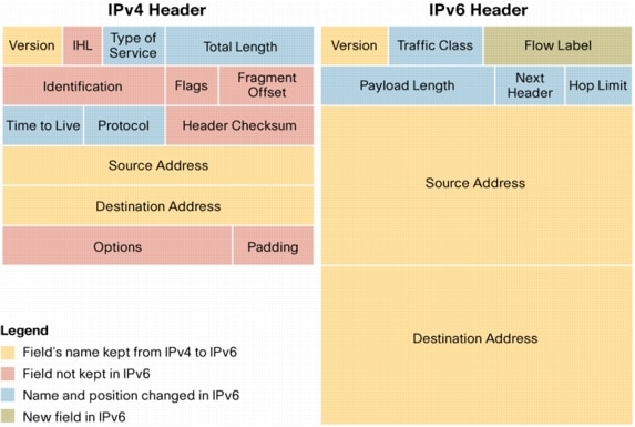 I got this off Cisco's white paper.As you can see in the NEXT header you can mark the NEXT header to be an extension header. Then on the next EXTENSION header you point to the next one etc. Till you are done with the extensions.http://www.cisco.com/en/US/technologies/tk648/tk872/technologies_white_paper0900aecd8054d37d.html
The explanation of what are those Extensions are about as vague as cryptic hieroglyph in Egypt is.Just try remembering Fragment - obviousAuthentication Header - used for IPSEC authenticityEncrypted security payload - used for IPSEC ESPWe said it was built in no ?TypesUnicast goes to one personBroadcast - no longer used in IPv6Multicast - goes to people.Anycast - This is clever and is assigned to many nodes. The device will talk to the closest node. So Anycast can be used for example for you to find out the closest video server and then stream from there. Or the closes CNN web server.when you have the zeros0000:0000:0000 you can double colon ::5c85 (this can only be used ONCE in the whole IP)you can also simplify 0000:0000:0000:0000 to 0:0:0:0:5c85reserved ones:: unspecified means nothing::1/128 this is the loopbackFF00::/8 FF like Fast Forward is for Multicast.FE08::/10 Local link private IP addressingEUI64 creates a unique IPv6Takes the MAC adds FF:FE in the middle and then the rest of the MACThis would be unique all over the internet.Self address discovery works byThe host sends an RS router solicitationThe Router sends an RA router advertisementThe RA advertisement includes the gateway and the prefix you should add to your IPv6 address.ND neighbor discovery which I guess is CDP if you are not a CiscoIPv6 support NDThe above means you don't need a DHCP. You can still add a DHCPv6set interface ge-0/0/1.0 family inet6 address fec0:0:0:2003::1/64pretty much same as IPV4 except you use inet6 and your address is ipv6Notice the above address is 64 bits and not 128 bits like an IPV6 lenght is.I'll come back to IPV6 later.ISISIt works similar fashion to OSPF.ISIS updates are PDUsL1 will route to other L1 or to L2sL2 route to other L2s in another area.The main difference between this and OSPF Is that OSPF has a central area called Area 0 that all other areas connect to (a backbone)ISIS does not have that limitation. You can create a lot more areas. That is why Service providers will generally use this protocol internally.Both use the Djukstra algorithmButh send hello packets or PDUsYou can summarize addressesYou can run authentication.HelloISIS sends hello and discovers if the neighbor is L2 or L1Link state PDUs are about the state of the links.CSNP complete sequence detail the whole table - designated will multicast themPSNP partial are requests for missing informationTLVs are the actual information about the routing. Here is an exampleCourtesy ofhttp://samrat-sammy.blogspot.com/2012/02/isis-packets-psnp.htmlHelloLevel one hellos are on multicast 01-80-C2-00-00-14Level 2 two hellos are on multicast 01-80-C2-00-00-15Desiganted will send every 3 secondsNon-designated every 9 secondsFields are.Circuit L1 ,L2 , L2/L1Source ID of the system that sent itHold Time before deathPDU lengthPriority 0 to 127 for the electionsLAN ID ?Link state build the databaseThey are sentWhen link goes downWhen new neighbor is in otownWhen the cost of a link has changedTLVEach TLV will have a TLV code specifying what information it contains.DIS electionDefault is 64The priority 0 means you don't participate.Hughest priority wins. 0- 127If there is a tie highest MAC wins.Unlike OSPF there is no backunlike OSPF there is an adjacency to all neighborsOPtional Metrics areDelayCostError on the linkwide-metrics-only increases the diameter above 256 hops.Configuring.By default all interfaces are L2 and L1 So you have to disable one or the other on the interface.#set protocols ISIS interface ge-0/0/0 level 1 disableEvery interface that will send ISIS must have the ISO family enabled on it.#set interface ge-0/0/0.0 family iso;to label the router for other routers use the Loopback interface#set interface lo0.0 family iso address 49.0001.0192.0168.0201.00>show isis interfacewill show which ones have which L1 or L2 on themit will also detail if this is a point to point or LAN or (passive for loopback)>show isis interface detailwill give you more details on it.like priority and adjecencies.>show isis database will give you the details on the neighborsLevel 1 neighborsLevel 2 neighbors.>show isis adjacencywill show you how the neighbors are up>show isis adjacency detailwwill give you more details like the IP address of the neighbor.>clear isis adjacency toronto will restart the adjacency with Toronto router.I guess you have an easy log>show isis spf log>show isis statistics>show isis routewill show you the database of the ISIS aas far as routes> show route protocol isiswill show you the routes that are in the routing table courtesy of ISISIf you want to run traceoptions.flag error detailflag hello detailflag lsp detailwill show you the data.If you want to troubleshoot. Don't look for IPsLook for physical problemsmistmatched L1 and L2 L1 won't bond with an L2 only with an L1/L2MTU 1492 and aboveBad ISO address on the loopback.RIPMaximum hop is 15RIPv1 supports classful routing onlyRIPv2 supports VLSM ie subnetting classlessBroadcast only updates are every 30 seconds. The broadcast is the whole table.25 routes per update.If the cost in hops to the network is lower it will add it.If the same router that broadcast the same network now has a higher cost to it then that goes in too(It will hold on adding it, till it gets a second update)RIPv2 has authentication simple or MD5RIPv2 can use Multicast 224.0.0.9Configurationset protocol rip group group_001 neighbor ge-0/0/0.2to export the static routes use a policyset policy-options policy-statement static_to_rip from protocol static then acceptset protocols rip group group_001 export static_to_ripsimilar to the OSPF or BGp you use a policy.Troubleshoot>show rip neighbor>show route protocol rip #will show you the routing table routes from RIP>show router advertising-protocol rip 10.0.0.2this will show me which routes am I advertising to 10.0.0.2>show route receive-protocol rip 11.11.11.11this will show me which routes I got from the other guy.show rip statistics #see if there is traffic.trace by flag errorflag update.I'll try to lab this at work .


No comments:
Post a Comment